
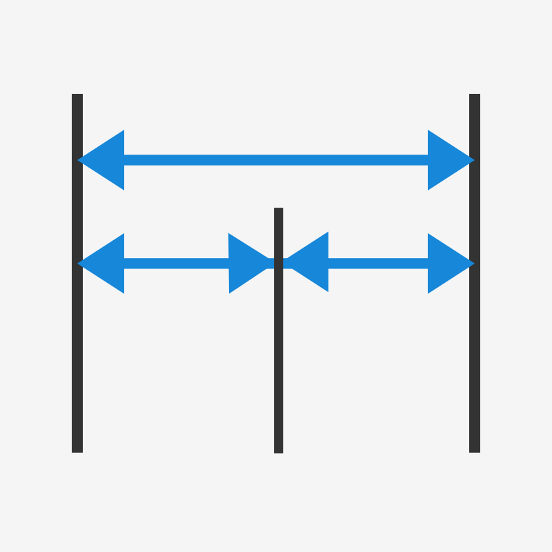
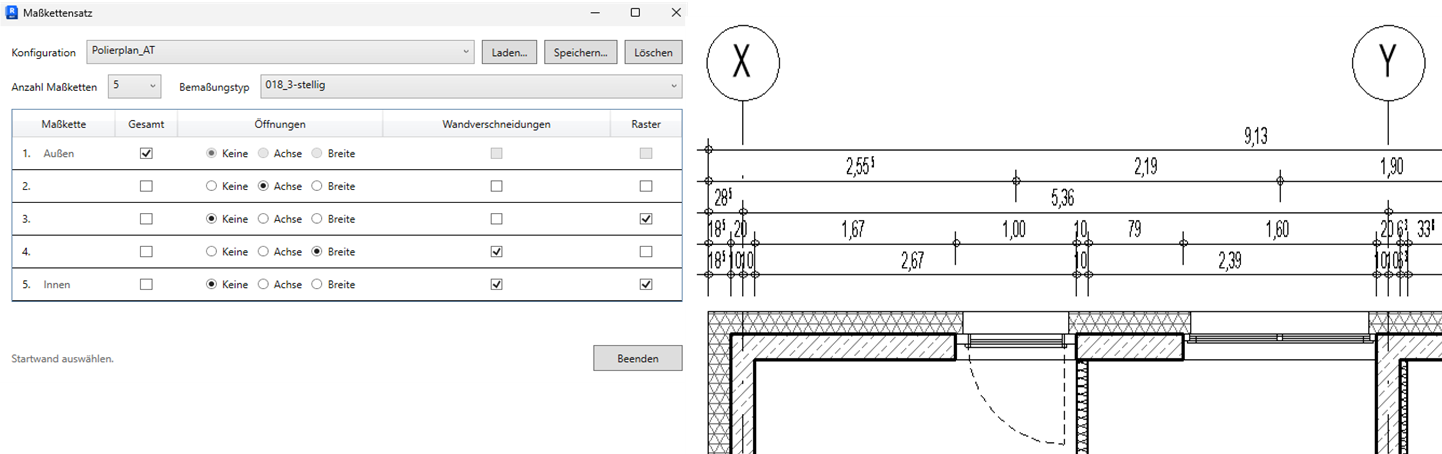
“Dimension String Set” (“Maßkettensatz”) automatically creates several parallel dimension strings along a straight wall. Use the configuration dialog to choose which openings, wall intersections, grids and overall dimensions to include.
To load this content, you need to allow the YouTube service.
In drawings, exterior walls are documented using several coordinated dimension strings. Almost all CAD programs can generate these sets of exterior wall dimensions natively. Once again, Revit cannot.
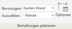
Revit’s automatic wall dimensioning (“Entire Walls”) creates only one dimension string at a time. To produce a complete dimension set, you have to change the settings repeatedly, select the inner wall followed by the outer wall, and position each string individually. Or, worse still, dimension everything manually.
Exterior walls require several levels of dimensions:
Opening widths
Opening centres
Wall intersections
Grid intersections
Overall dimension
On long façades with many doors, windows, intersecting walls and grids, this quickly becomes tedious. References may be missed, the wrong options selected, or dimension strings placed at inconsistent distances.
“Dimension String Set” fills this gap and creates all the required dimensions in a single operation.

Create multiple dimension strings in one operation
Automatically create an overall dimension
Keep consistent spacing between dimension strings
Reuse saved configurations
Reduce manual selection and the risk of errors
Dimension multiple walls consecutively
To run the add-in, open a floor plan and click the Maßkettensatz button.
The configuration dialog opens.
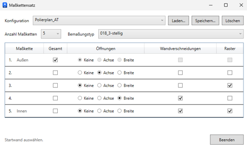
Select a dimension type
Select the required linear dimension type at the top of the dialog.
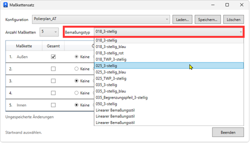
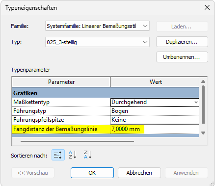
The selected type also controls the spacing between dimension strings through its Dimension Line Snap Distance parameter.
Configure dimension strings
First, select the number of dimension strings.
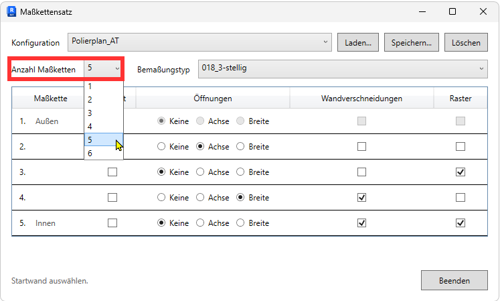
Each row in the matrix represents a separate dimension string.
 The configuration corresponds to Revit’s built-in automatic dimensioning options:
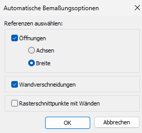
Rows with no options selected and selections with no matching elements do not create a dimension string. For example, this happens if a row is configured to dimension grids only, but no grid intersects the wall.
The top-to-bottom order determines how the strings are arranged from the inside out.
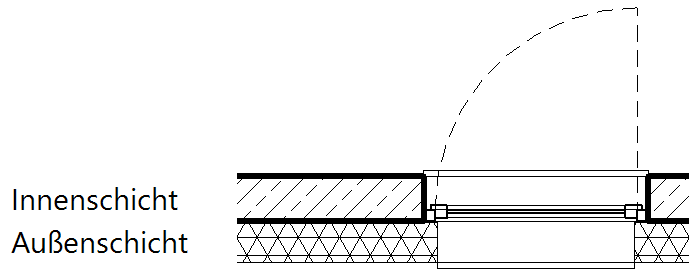
Inner and outer layers: With our content, multilayer walls are modelled using two separate layers.
The tool dimensions all elements in the inner layer, then finds the adjacent outer wall and dimensions it.
Save and load configurations
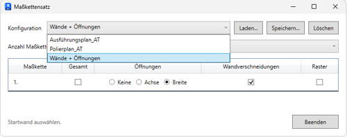
Use the drop-down menu to switch between configurations.
Save (Speichern) saves the current combination of dimension strings and the selected dimension type as a JSON file.
Load (Laden) lets you reuse saved settings. This allows you to prepare different dimensioning standards for façades, interior walls or specific project requirements.
Remove (Entfernen) deletes both the entry and the corresponding JSON configuration file.
Create a dimension set
Now select an inner wall.

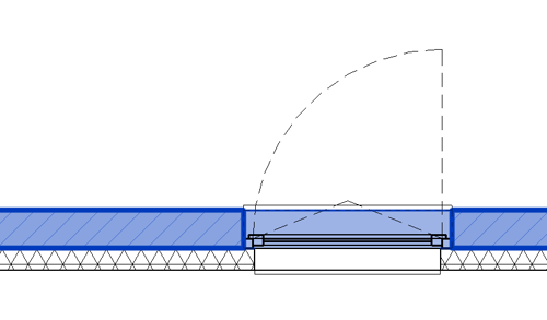
Then click a point near the side on which you want to place the dimensions:

The point determines:
which side of the wall the dimension strings are placed on;
the distance between the wall and the first dimension string.
The tool automatically finds the references enabled in the configuration and creates dimension strings parallel to the selected wall.
Additional strings are placed further out at consistent intervals. If no suitable detail reference is found for a configured row, that row is skipped.
After the dimensions have been created, the tool remains active and the configuration window stays open.
You can immediately select the next wall, or choose a different configuration and continue.
Click Exit (Beenden) or press Escape to finish.
1.0.9.14
Press F1 to open the BIMpedia article.
New icon.
The dialog remains active while the tool is in use. This allows you to apply different dimensioning configurations in a single session.
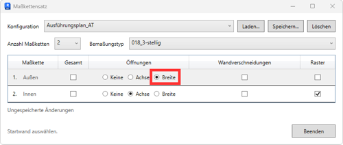
Dimensioning opening widths in the outer layer returns the structural opening width, not the clear opening width at the insulation layer:

The tool currently works in floor plan views only.
Only straight walls are supported.
Elements in linked Revit models are not evaluated.
If you have any problems, questions, ideas or suggestions, please contact our customer service team. We welcome your suggestions for improvement!