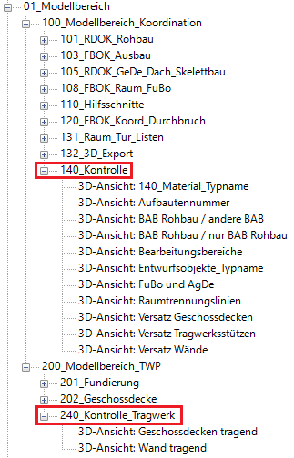
The 3D views under the sections 140_Check and 240_Check_Structure are used to assist with model verification and general model checks. The visibility and graphical representations of the views are controlled by optimized view templates. Visibility is primarily controlled by turning model categories, filters, and editing areas on or off.
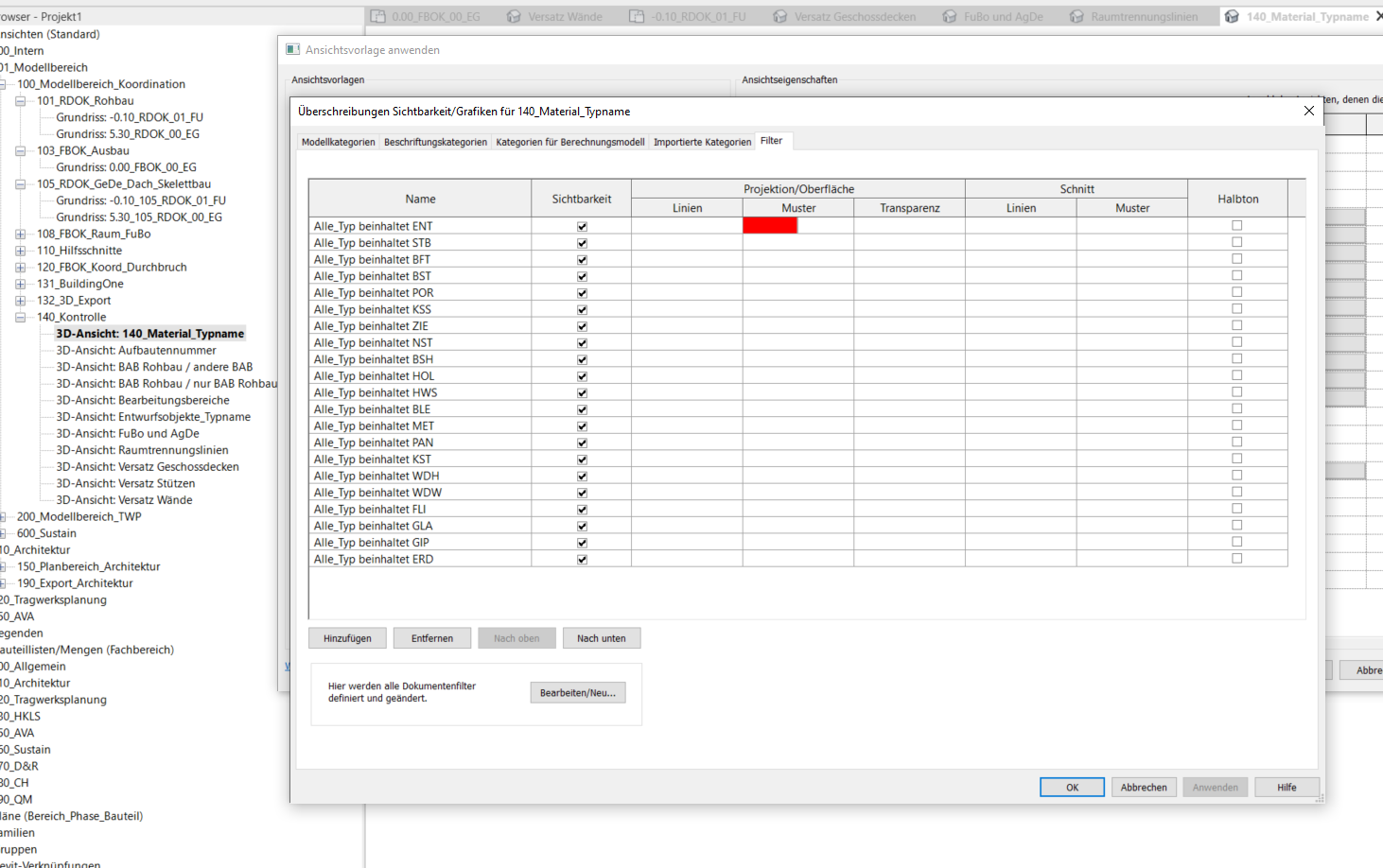
The filters set up in this template allow the user to show or hide items based on the material name, or to overwrite them graphically, in order to verify whether the material has been assigned correctly.
All objects whose type names include the following material codes can be enabled or disabled using filters:
- ENT (Draft)
- RC (Reinforced Concrete)
- BFT (Precast Concrete)
- HFT (semi-precast)
- BST (Concrete Block)
- POR (aerated concrete)
- KSS (calcium silicate block)
- NST (Natural Stone)
- GLT (Glued laminated timber)
- HOL (Wood/Solid wood)
- HWS (Wood-based material)
- BLE (sheet metal)
- MET (Metal)
- PAN (Panel)
- KST (Plastic)
- WDH (Rigid Thermal Insulation)
- WDW (Soft thermal insulation)
- FLI (Tiles)
- GLA (Glass, profiled glass, glass block)
- GIP (Plaster, drywall)
- ERD (Ground)
Verifiable using this view:
- Useful materials
- Remove unused items
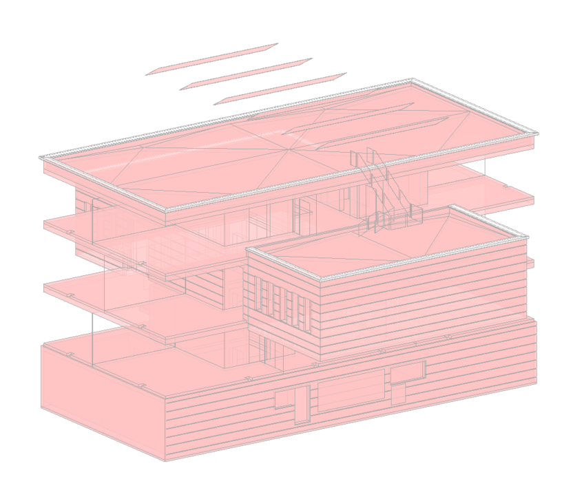
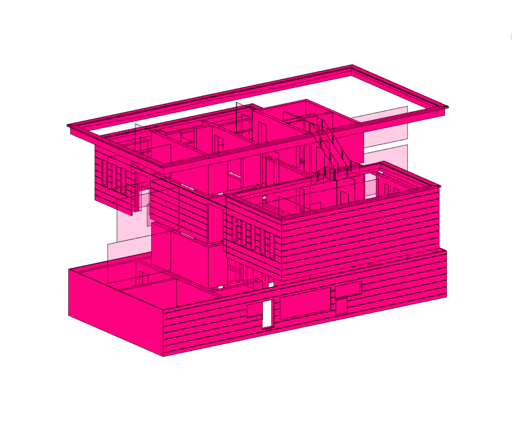
All objects in the "Roofs, Floor Slabs, and Walls" model category are displayed in halftone with 20% transparency. Objects without a structure number are overlaid in red.
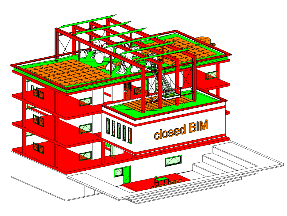
All structural elements (foundations, load-bearing floor slabs, structural frames, structural columns, load-bearing walls, and openings) are displayed in red. All other model categories are displayed in green. Objects in the General model category are displayed in orange.
In projects, it often happens that components are placed on the wrong elements—for example, openings on floor slabs instead of on the floor slab, etc. As a result, these openings are not cut out of the floor slab, which subsequently leads to major problems.
Verifiable using this view:
- Object Assignment to Processing Areas
- Openings
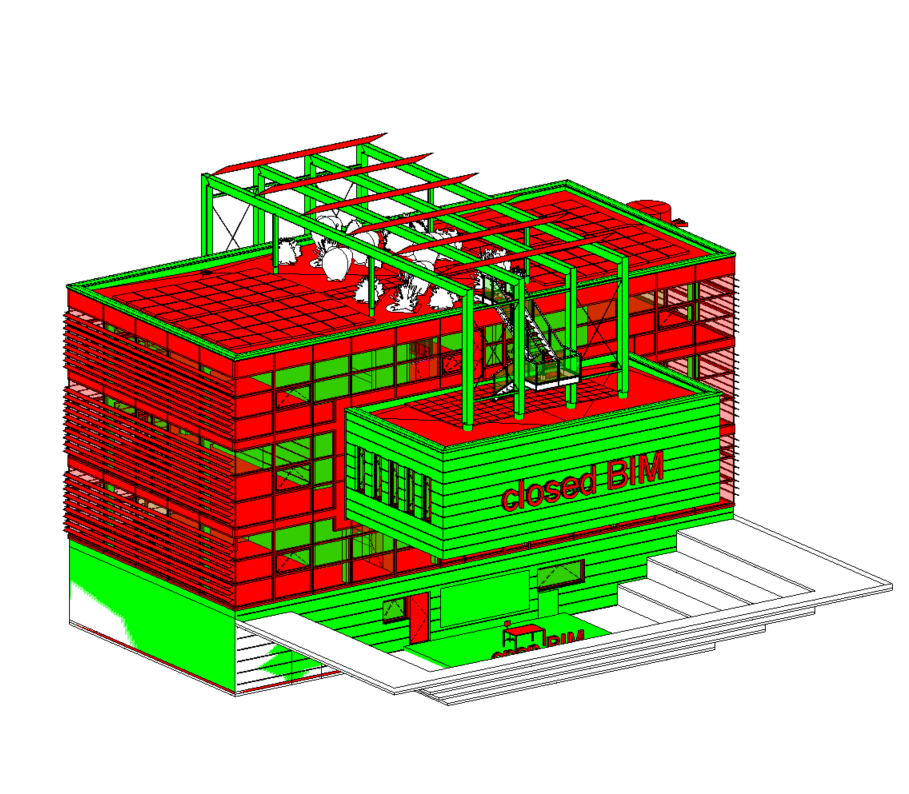
All structural elements (foundations, floor slabs, structural frames, structural columns, walls, openings) are displayed in green. All other model categories, as well as non-load-bearing walls and floor slabs, are displayed in red.
This check view works similarly to the 140_Check_BAB_Shell / other BAB. The difference is that in this view, only the families relevant to the shell are active. Shell elements are displayed in red, and elements that intersect the shell are displayed in green.
Only objects assigned to the BAB shell construction are displayed here: GREEN means: OK; RED means: The object should at least be checked.
Verifiable using this view:
- Object assignment to processing areas
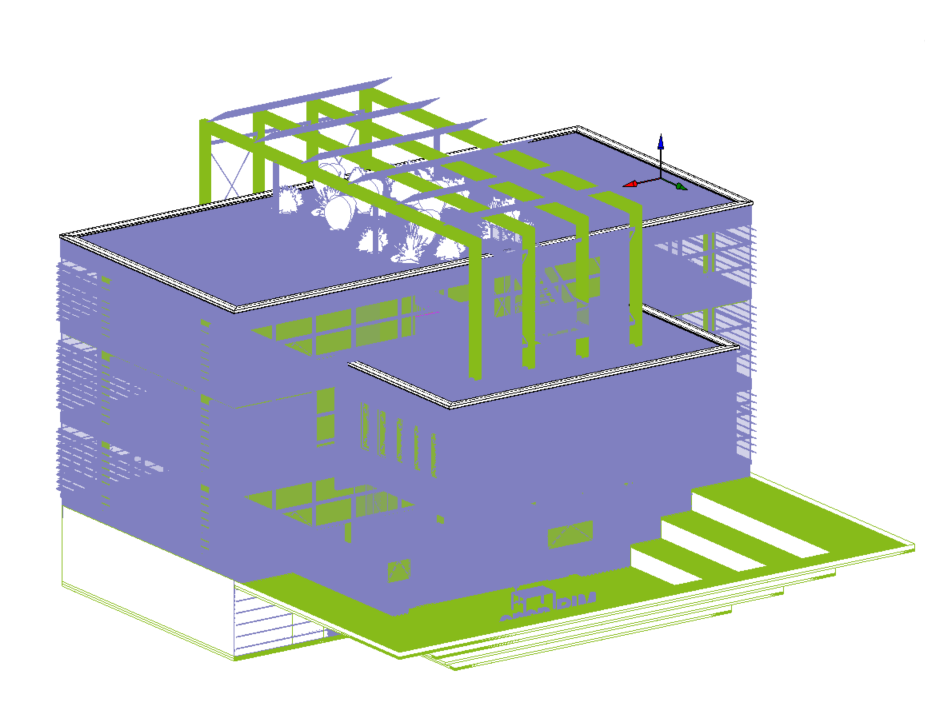
This view template for 3D views allows you to see which elements are assigned to the respective editing areas. These are displayed in the same color. This view template is only available if a new project is created using the central file rather than the template file.
All objects whose type name contains "ENT" will be displayed. All other objects will be hidden.
At the start of a project, draft objects are often used because there is not yet a precise definition for items such as doors or floor structures. These objects are replaced with the actual elements as the project progresses. However, it can happen that such elements are overlooked.
If the view template 140_Draft_Objects is used, only those elements that have been defined as draft elements are displayed. Ideally, once a certain project phase is reached, the view should be empty when the view template is applied.
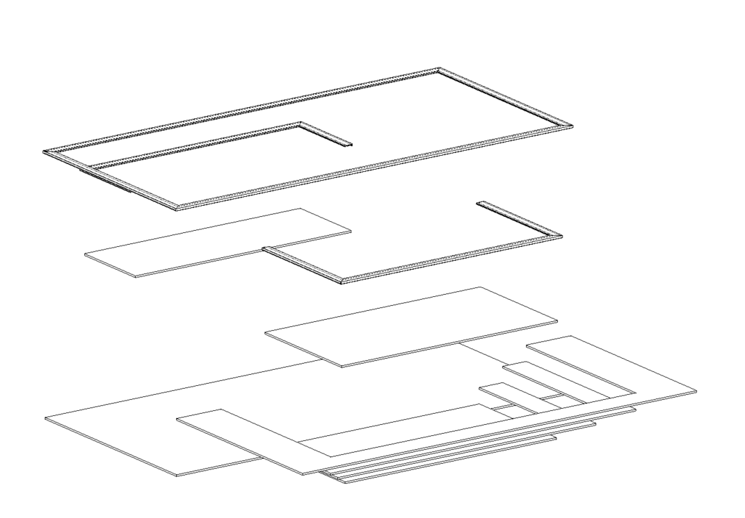
All ceilings and floor slabs are displayed. Floor slabs (not floor surfaces) are not displayed.
Verifiable using this view:
- Check number of elements (duplicate elements)
- Offset
- Load-bearing/non-load-bearing
- Intentional offset Check box
- Room boundary checkbox
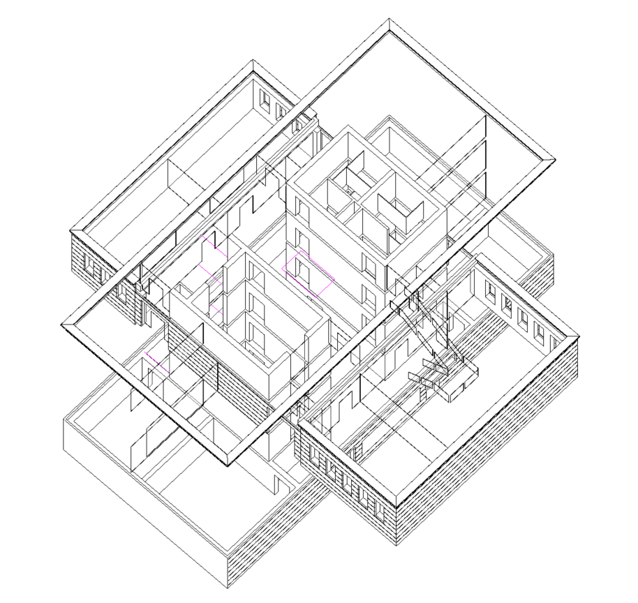
The model categories Skeleton Structure, Structural Columns, Stairs, Doors, Walls, Facade Elements, Facade Posts, Foundations, Trusses, Communication Devices, Lines, and Drafting are displayed with 50% transparency. Room partition lines are displayed in pink to make it easier to identify and verify room boundaries.
Verifiable using this view:
- Room boundaries
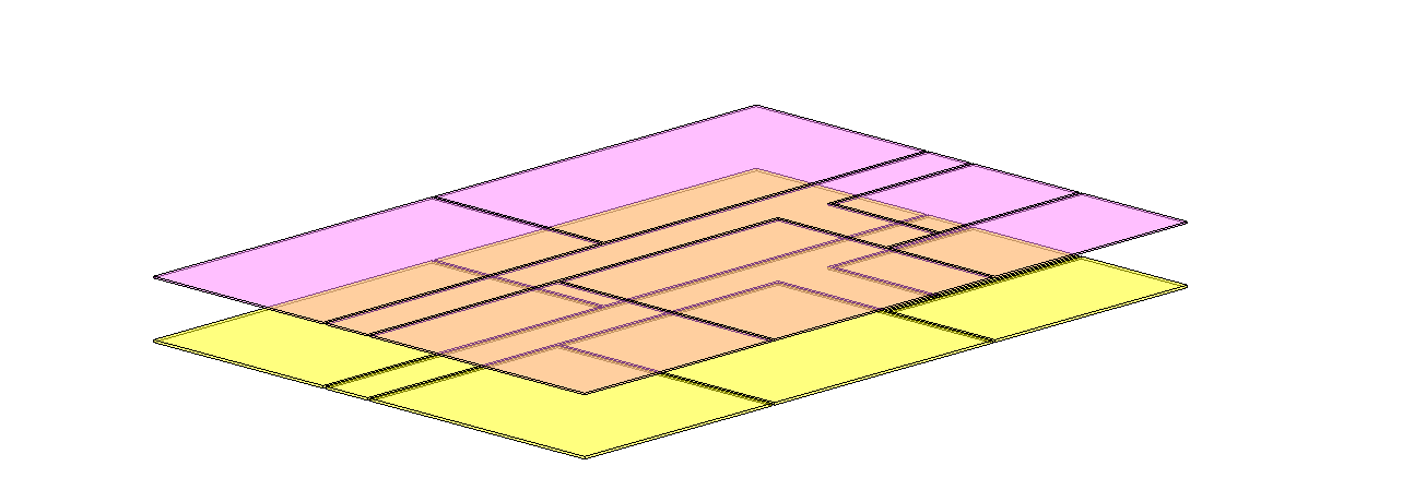
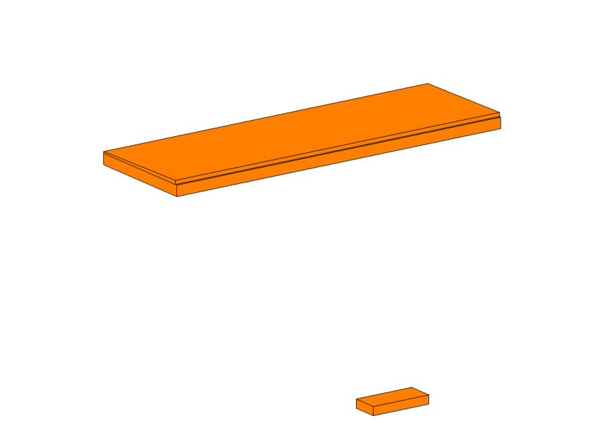
In this view, floor slabs with an offset are displayed in orange. This allows us to check whether the floor slabs are at the correct level and whether the offset is correct or necessary. Floor slabs without an offset are hidden.
In Revit, it is necessary to explicitly define whether a component is a structural or non-structural floor slab. Unfortunately, it is very easy to overlook this definition. This view template helps identify whether an incorrect assignment has been made.
Verifiable using this view:
- Indentation
- Check the "Intentional offset" box
- Check number of elements (duplicate elements)
- Check the "Boundary" checkbox
In this view, structural columns with an offset are shown in red. This allows us to check whether the columns are on the correct level and whether the offset is correct or necessary. Structural columns without an offset are hidden.
Verifiable using this view:
- Indentation
- Check the "Intentional offset" box
- Check number of elements (duplicate elements)
- Check the "Boundary" checkbox
In this view, walls with an offset are displayed in magenta. This allows us to check whether the walls are on the correct plane and whether the offset is correct or necessary. Walls without an offset are hidden.
NOTE: First use the b.i.m.m Experience Tool to set the wall parameters: 173_100_117_Offset from Top Reference, 173_100_117_Offset from Bottom Reference); For walls where an offset is actually intended (secondary, non-load-bearing walls), the >Offset parameter can be checked! (This will hide the wall.)
Verifiable using this view:
- Indentation
- Check the "Intentional offset" box
- Check number of elements (duplicate elements)
- Check the "Boundary" checkbox
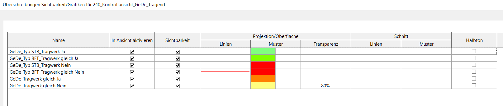
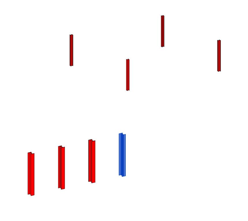
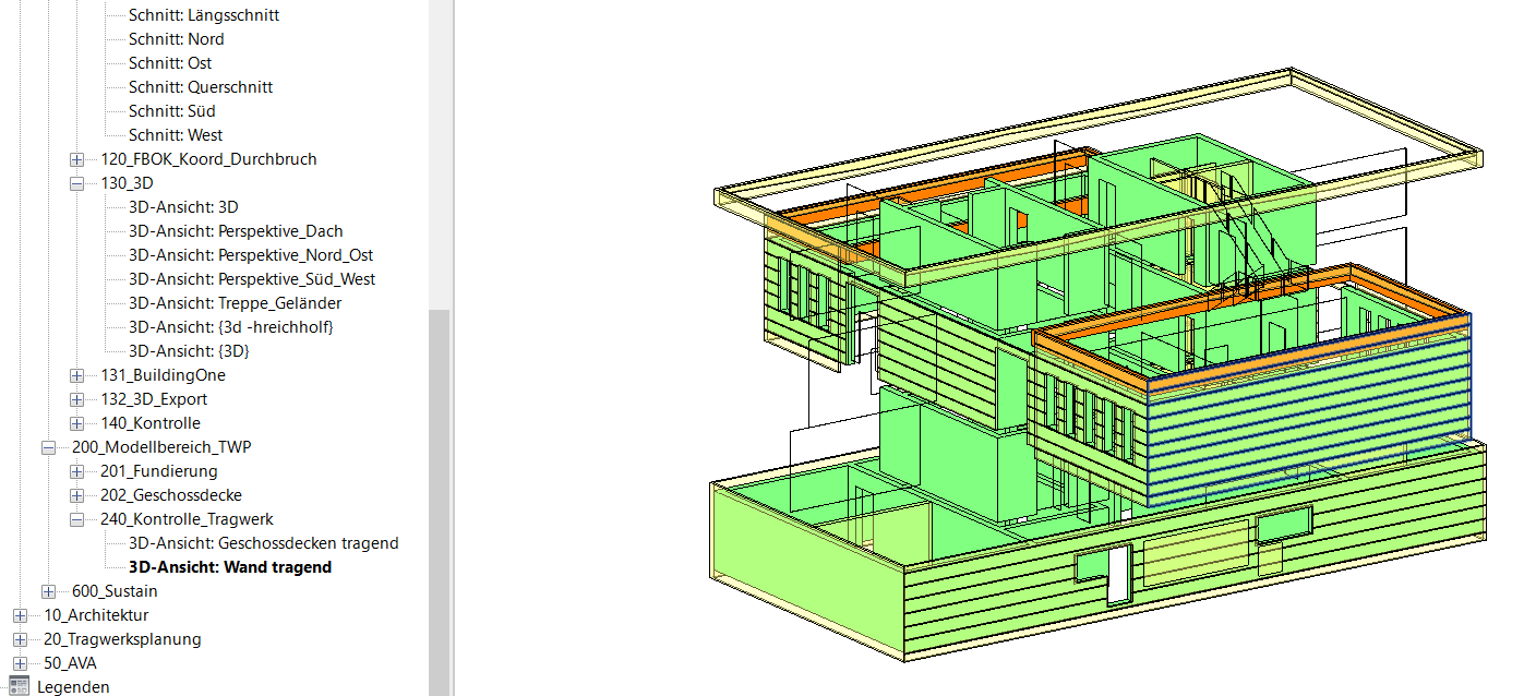
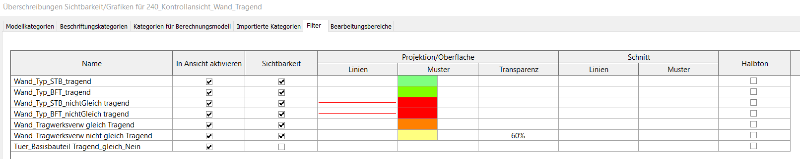
This view includes:
- All load-bearing walls (designated by the abbreviations STB, HFT, and BFT) are shown in green.
- All non-load-bearing walls (with the abbreviations STB, HFT, and BFT) are shown in red.
- All load-bearing walls with a different material code are shown in orange.
- All non-load-bearing walls with a different material code are shown in yellow.
- All other categories are hidden.
In Revit, it is necessary to explicitly specify whether a component is a structural or non-structural element. Unfortunately, it is very easy to overlook this step. This view template helps identify whether an incorrect assignment has been made.
Verifiable using this view:
- Material
- Load-bearing/non-load-bearing
- Offset/Intentional offset Check the checkbox
- Check number of elements (duplicate elements)
- Room boundary checkbox
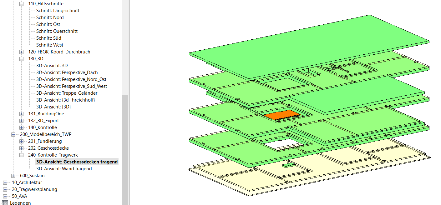
This view includes:
- All load-bearing floor slabs (designated STB and BFT) are shown in green.
- All non-load-bearing floor slabs (with the abbreviations STB and BFT) are shown in red.
- All load-bearing floor slabs with a different material code are shown in orange.
- All non-load-bearing floor slabs with a different material code are shown in yellow.
- All other categories are hidden.
In Revit, it is necessary to explicitly define whether a component is a structural or non-structural element. Unfortunately, it is very easy to overlook this step. This view template helps identify whether an incorrect assignment has been made.
Verifiable using this view:
- Material
- Offset/Intentional offset: Check the box
- Check number of elements (duplicate elements)
- Room boundary checkbox