This add-in allows you to automatically place families according to configurable, rectangular patterns. This enables a large number of placements to be carried out efficiently, based on rules, and without errors.
To load this content, you need to allow the YouTube service.
During the planning process, certain elements—such as ventilation outlets, light fixtures, or sensors—often need to be placed in multiple rooms according to a fixed pattern. This repetitive task can quickly lead to errors and waste valuable time.
- Automatic placement of any number of families according to a configurable pattern
- Simultaneous placement in multiple rooms or MEP rooms is possible
- Placement based on fixed distances, flexible distributions, or grid counts
- Installation height can be defined as an offset from the plane or as an absolute value
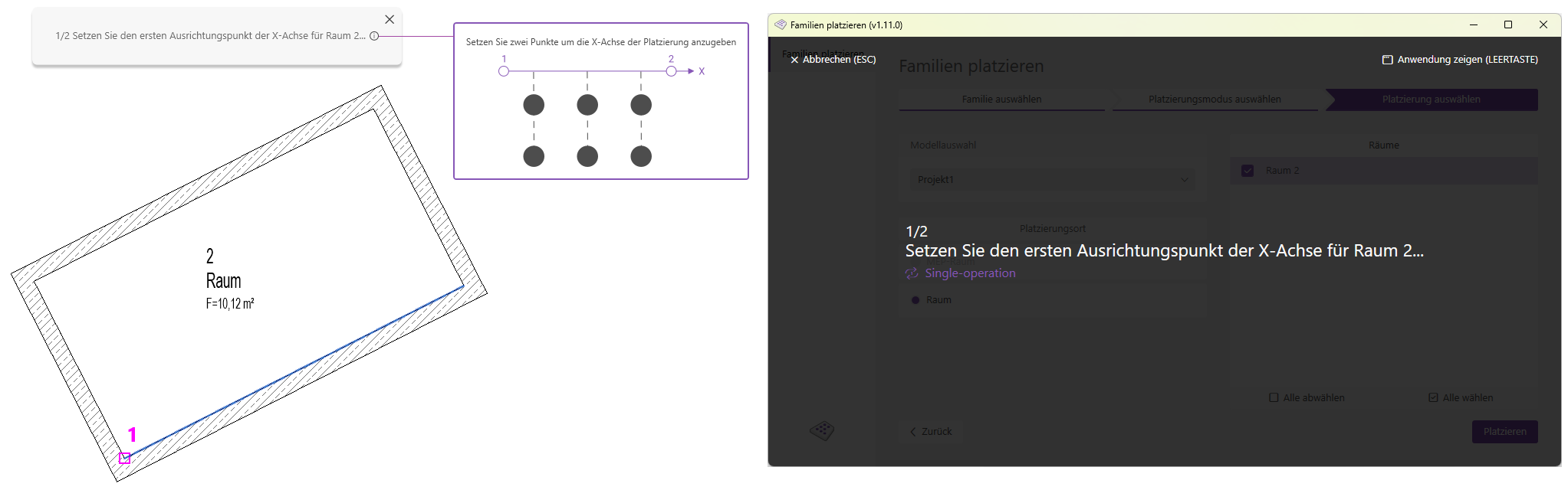
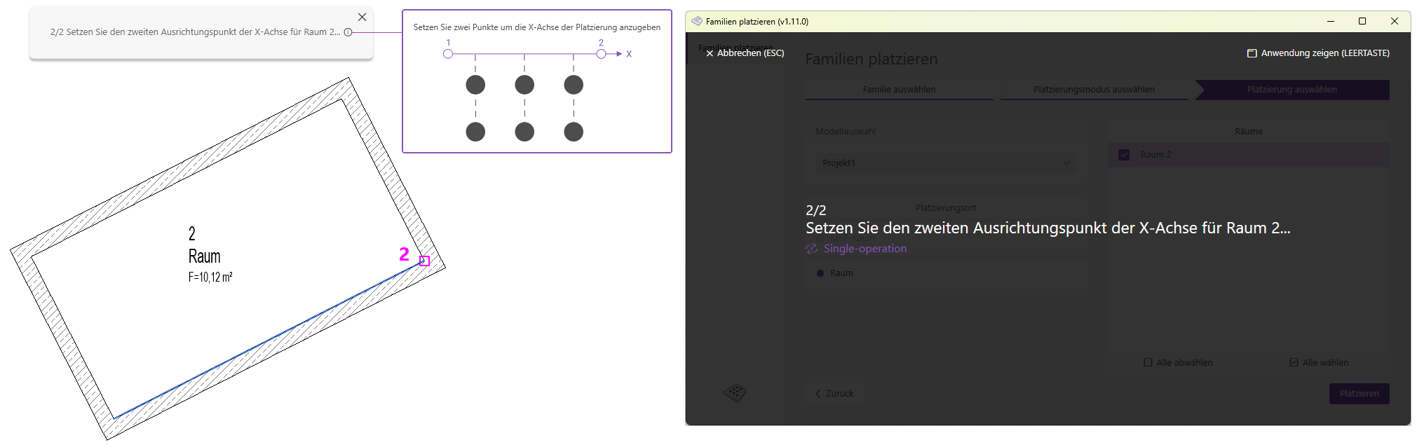
- Placement also possible in rooms that are not orthogonal to the project coordinate system
There are three placement modes available. Use the tabs to navigate through the modes and view the feature overview for each mode.
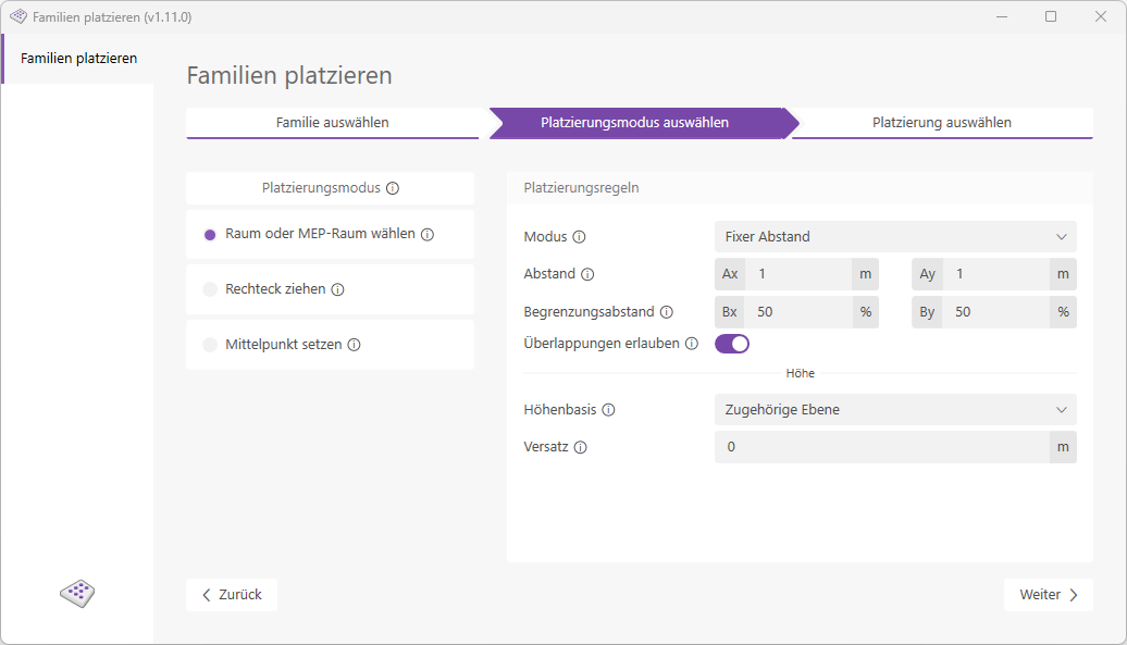
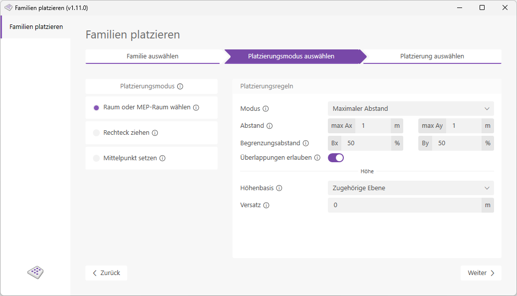
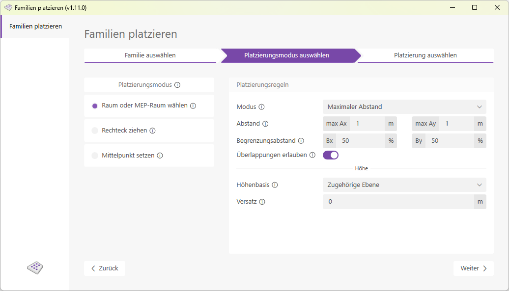
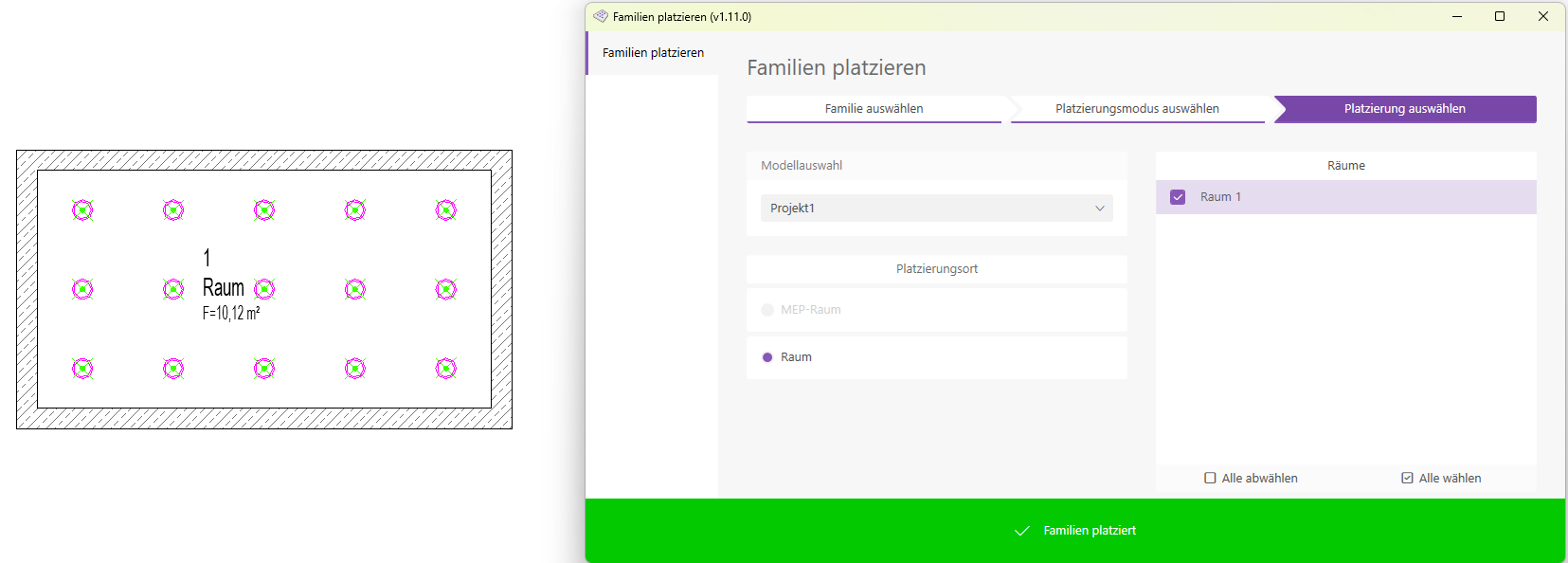
In the "Select Room or MEP Room" placement mode, all rooms in the model are listed. You can select as many rooms as you like and populate them with the desired families based on your settings.
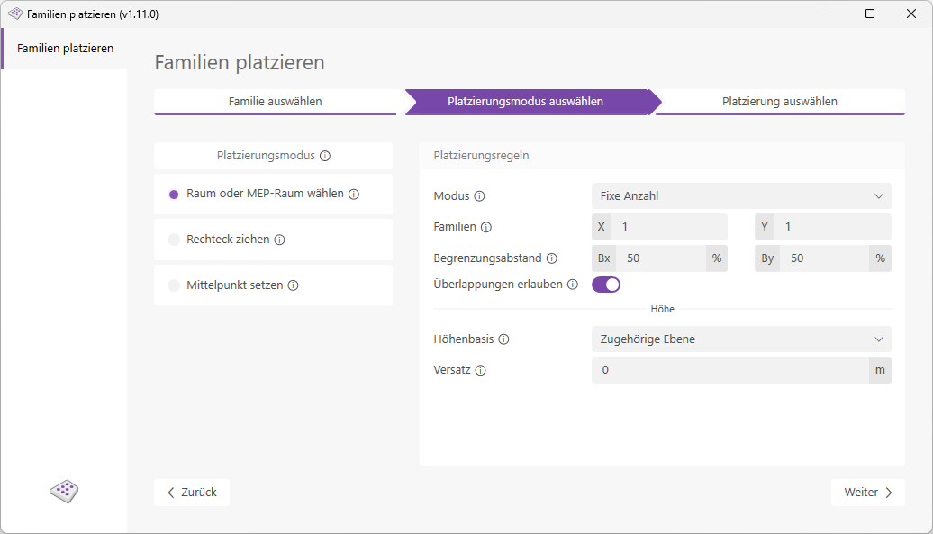
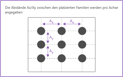
The following placement rules can be configured:
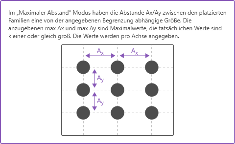
- Fixed Distance Control Mode:
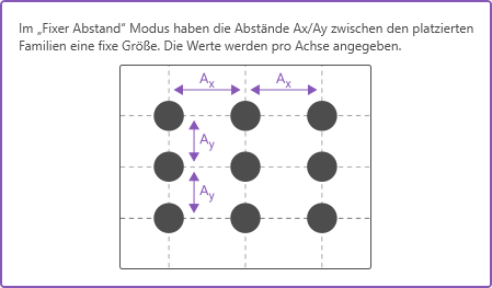
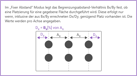
Result: Elements are placed at 0.5, 2.5, and 4.5 meters. The distance between the elements is therefore a fixed 2 meters, while the distance to the boundary is variable (but no more than 1 meter).
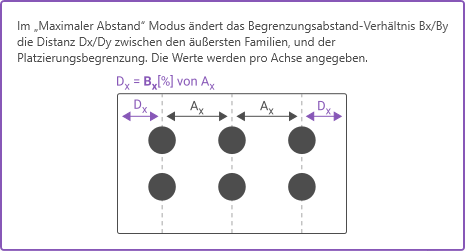
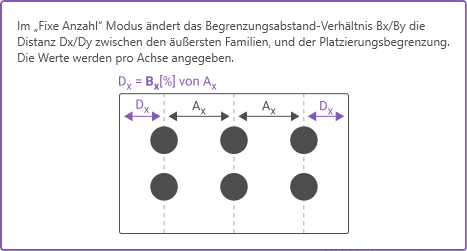
Result: Elements are placed at 0.83 / 2.5 / 4.17 meters. The distance between the elements is x, and the distance to the room boundary is 50% of x. For a room width of 5 meters: x = 5/3 = 1.67 meters
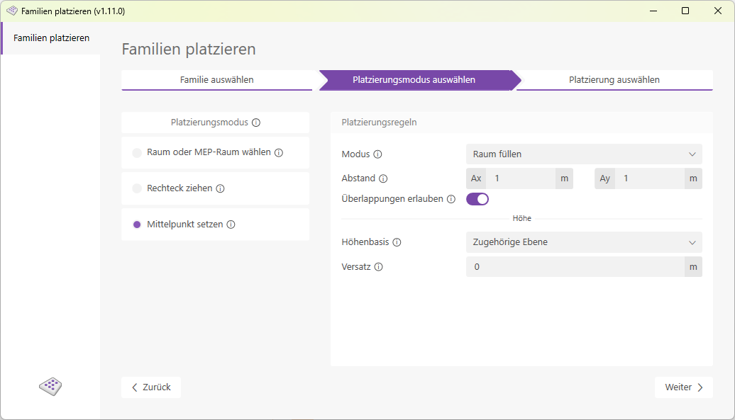
The "Allow Overlap" switch determines whether the placed families are allowed to overlap with the room boundary.
Select one of five options here to define the base for the placement height.
- Absolute Zero
Place at elevation zero, starting from the project base point. - Lower room boundary (floor slab)
: Place at the lower room boundary or floor slab. - Upper room boundary (ceiling)
: Place at the upper room boundary or ceiling. - Associated Level
: Place at the associated level of the respective placement area. - Selected Level
Place on a selected level.
Relative offset from the elevation baseline.
Note:
- For irregularly shaped rooms, placement generally follows the same two-axis method. Elements that would be placed "outside" the room as a result are not placed.
- If an element to be placed would happen to be placed exactly at the location of a (room-bounding) column, for example, that element cannot be placed automatically. If the column is not defined as room-bounding, the element is placed at the location of the column.
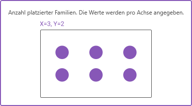
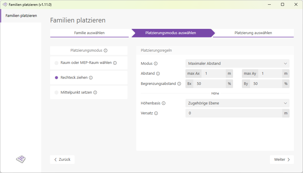
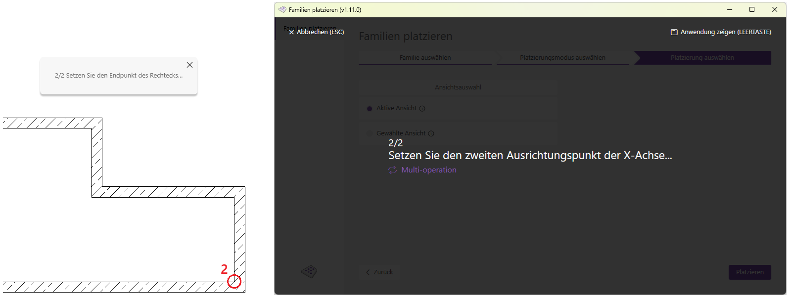
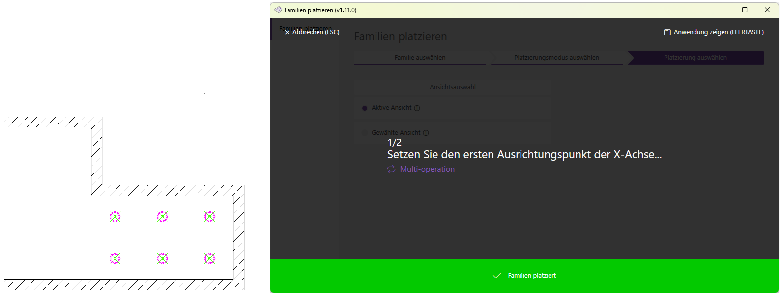
In Rectangle Placement Mode, you can define a rectangle directly in Revit by selecting a start point and an end point. This rectangle is then filled with the desired families according to the settings you have specified.
The following placement rules can be configured:
- Fixed Distance Control Mode:
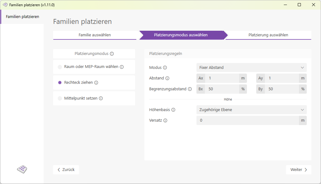
Result: Elements are placed at 0.5, 2.5, and 4.5 meters. The distance between the elements is therefore a fixed 2 meters, while the distance to the boundary is variable (but no more than 1 meter).
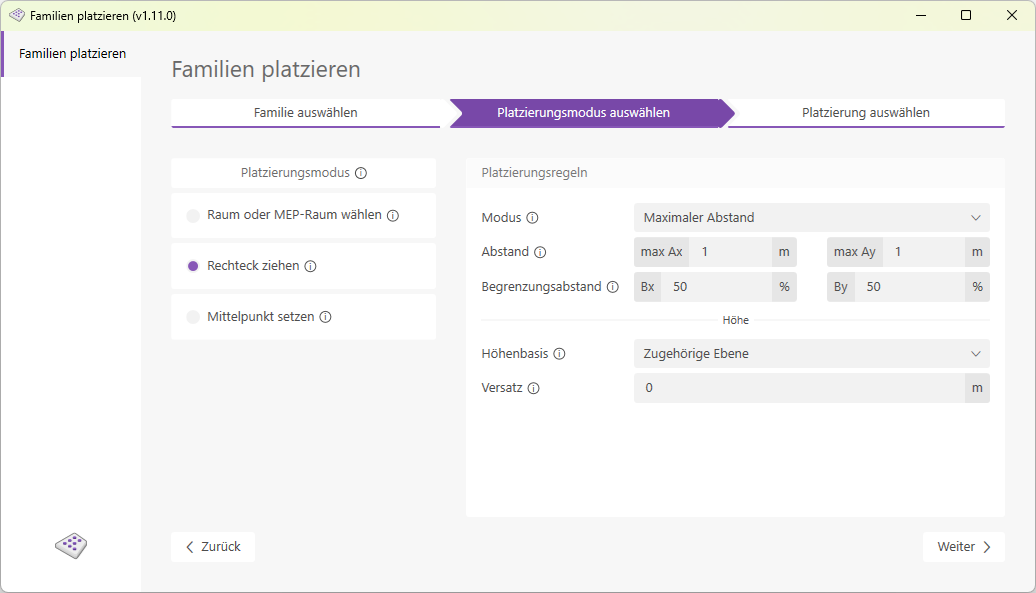
Result: Elements are placed at 0.83 / 2.5 / 4.17 meters. The distance between the elements is x, and the distance to the room boundary is 50% of x. For a room width of 5 meters: x = 5/3 = 1.67 meters

Select one of five options here to define the base for the placement height.
- Absolute Zero
Place at elevation zero, starting from the project base point. - Lower room boundary (floor slab)
: Place at the lower room boundary or floor slab. - Upper room boundary (ceiling)
: Place at the upper room boundary or ceiling. - Associated Level
: Place at the associated level of the respective placement area. - Selected Level
Place on a selected level.
Relative offset from the elevation baseline.
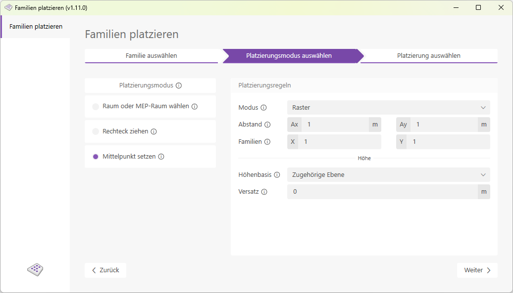
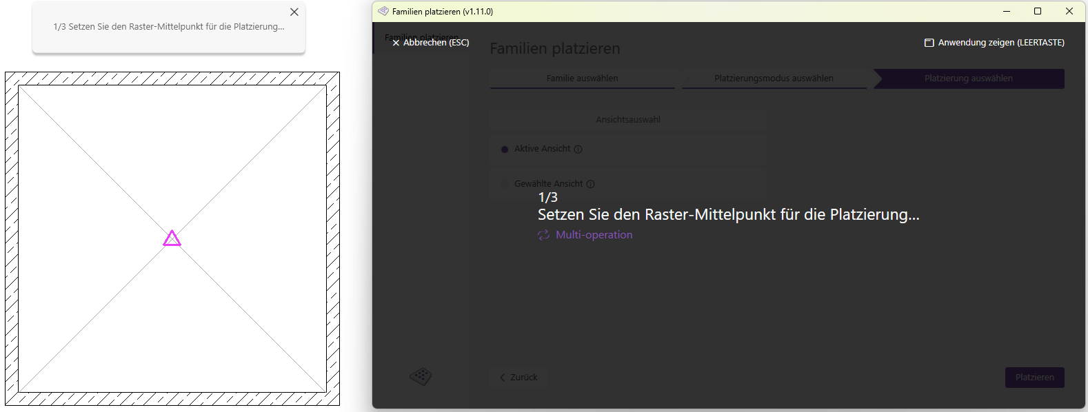
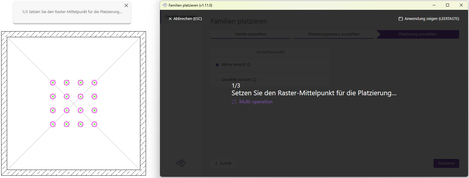
In "Set Center" placement mode, a point selected in the Revit user interface serves as the basis for placement.
The following placement rules can be configured:
- Grid mode:
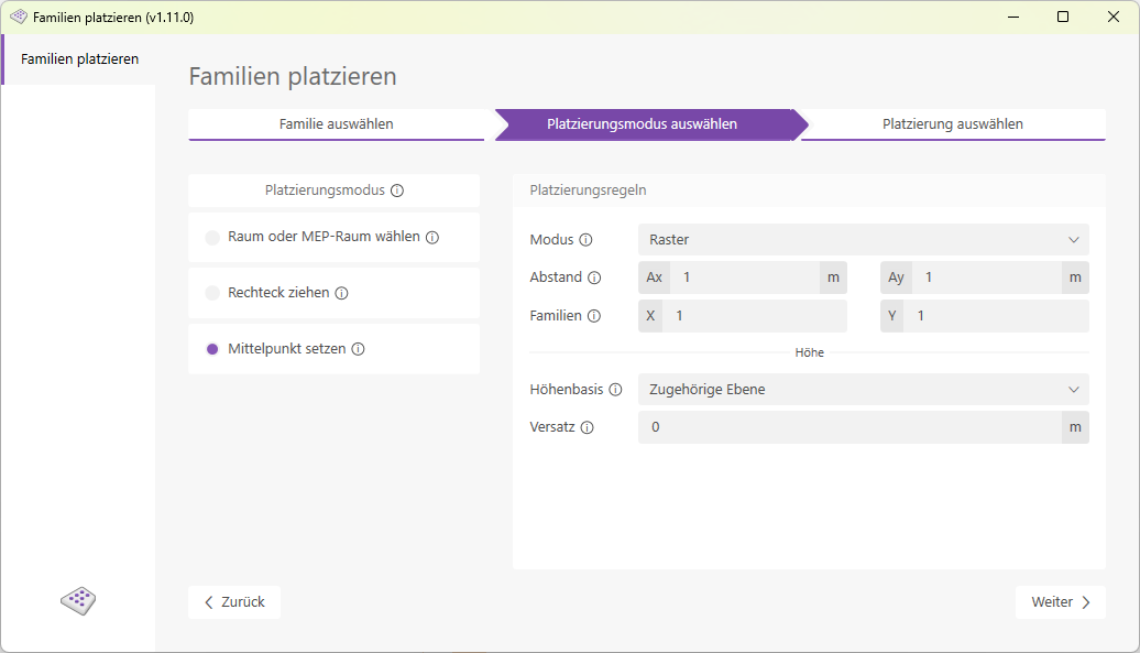
Select one of five options here to define the base for the placement height.
- Absolute Zero
Place at elevation zero, starting from the project base point. - Lower room boundary (floor slab)
: Place at the lower room boundary or floor slab. - Upper room boundary (ceiling)
: Place at the upper room boundary or ceiling. - Associated Level
: Place at the associated level of the respective placement area. - Selected Level
Place on a selected level.
Relative offset from the elevation baseline.
- Click the "Place Families" button to launch the add-in.
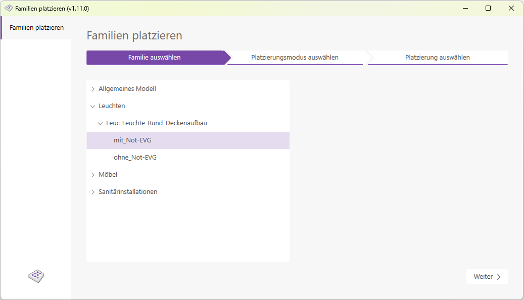
- Select one of the three placement modes and configure the placement rules.
- Click the Next button once you have configured all settings.
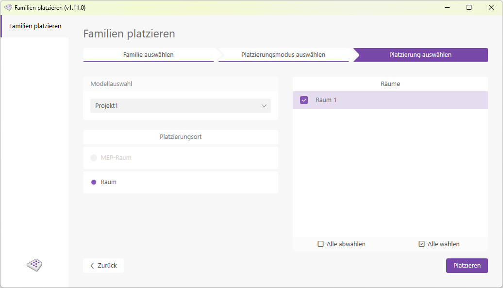
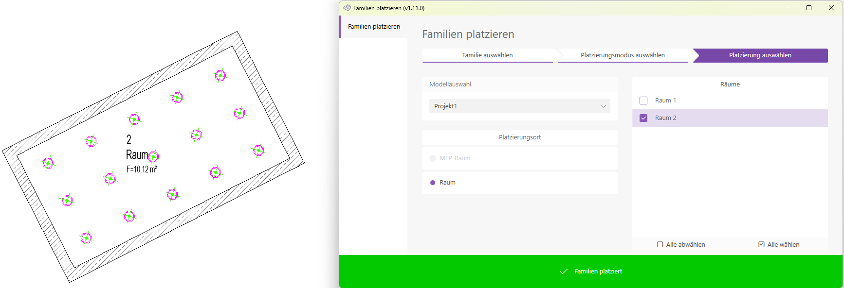
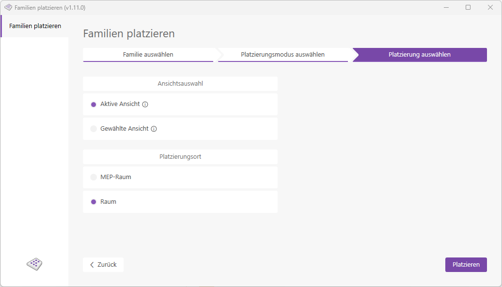
- The final page, "Select Placement," will now open.
- Select the model and room type, then choose as many rooms as you like for placement.
Next, click Place.
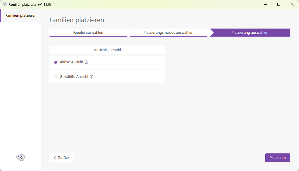
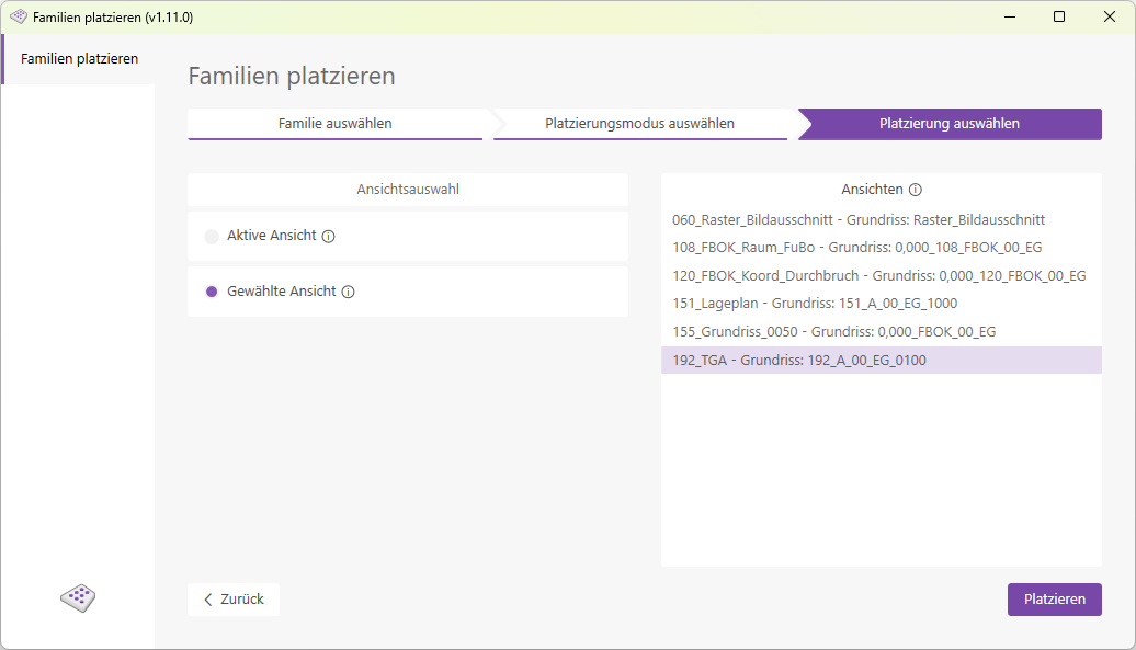
- Choose between the "Active View" and "Selected View" placement modes. In "Selected View" mode, all views in the model are displayed in a list, and the selected view is then opened for you.
Note: You are still in selection mode! You can now define new rectangles and place families as often as you like. The process does not end until you exit it using the Escape key or the Cancel button, or when you close the add-in.
- Choose between the "Active View" and "Selected View" placement modes. In "Selected View" mode, all views in the model are displayed in a list, and the selected view is then opened for you.
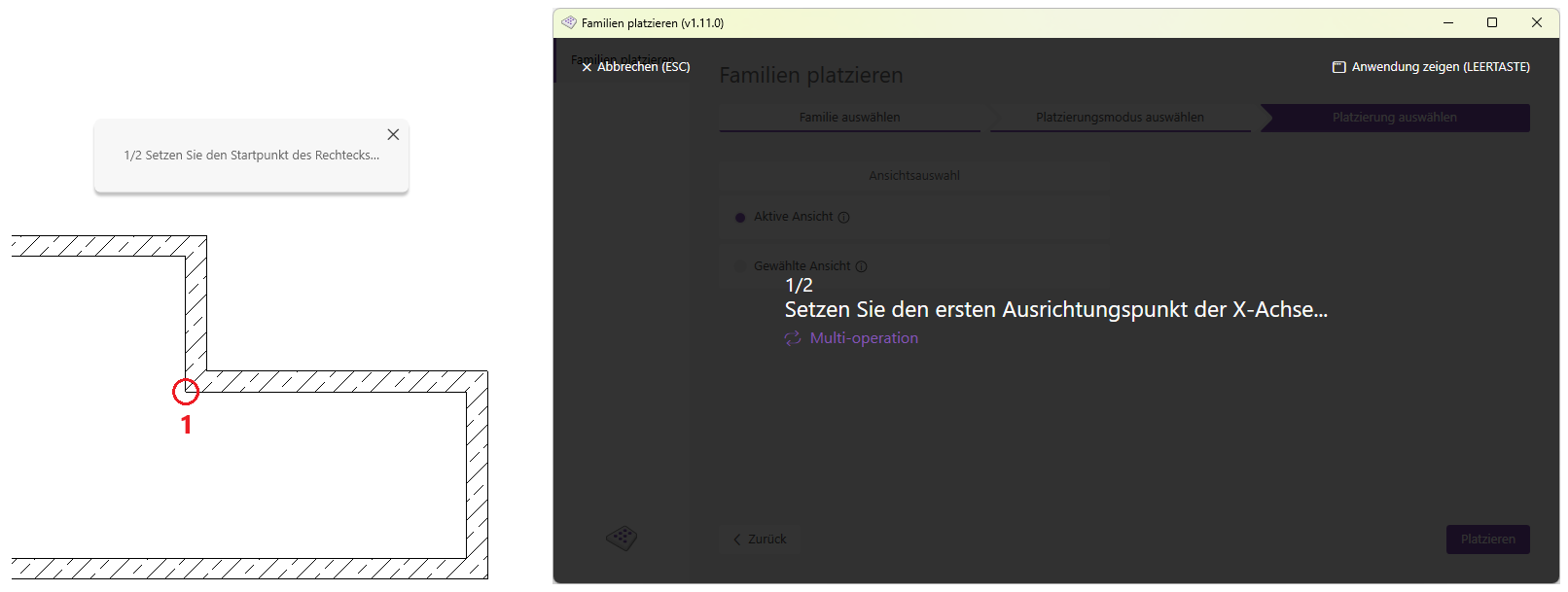
- Click the Place button to enter selection mode.
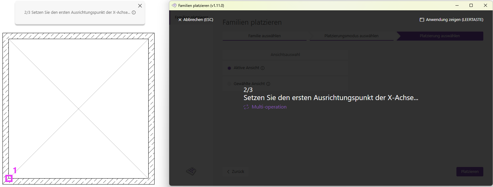
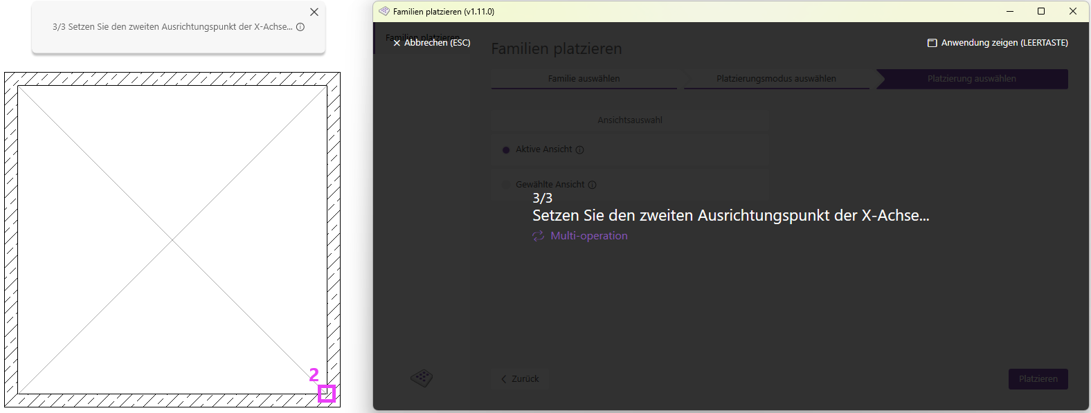
- You are now in selection mode; first select a center point for placement. In the next step, select a start point and an end point; the resulting line indicates the placement direction. The families will now be placed according to the settings you have made.
Note: You will remain in selection mode after placing! You can now define new center points and place families as often as you like. The process does not end until you exit it using the Escape key or the Cancel button, or when you close the add-in.
1.13.0.0
- Revit 2026.0 through 2026.4 is now supported.
- The info icon opens the BIMpedia article.
- Pressing the F1 key opens the BIMpedia article.
If you have any problems or questions, or if you have ideas or suggestions, please feel free to contact our customer service team. We look forward to hearing your suggestions for improvement!