The "Place Combinations" feature allows you to create combinations of families—such as outlets and light switches—on configurable virtual grids and then place them in the model. Both vertical and plane-based placement are supported.
To load this content, you need to allow the YouTube service.
Placing numerous components, such as switches and outlets, requires a significant amount of manual work. Arranging them in a horizontal or vertical grid is often necessary, but this cannot be easily achieved in Revit.
Setting up such combinations is time-consuming, and reusing them later is virtually impossible. The position of the symbols also has to be adjusted manually each time—which takes time and increases the risk of errors.
- Manage recurring combinations in one place
- Use them over and over again
- Define the placement of graphics so they always look the same.
- Transfer layouts to a new project and save even more time.
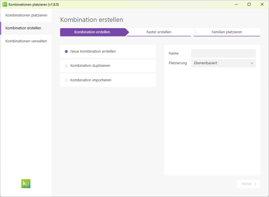
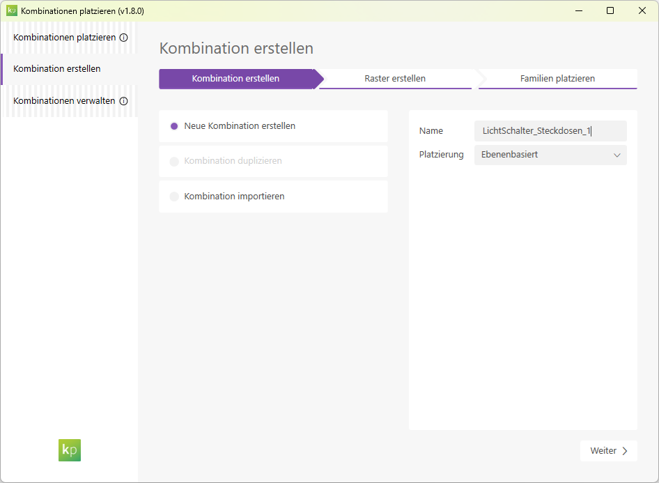
Create combinations
- Create as many combinations of elements as you like.
- Define both vertical and workplane-based combinations. This allows you to create complex switch groups on the wall and directly on component surfaces.
- Simultaneous definition of combinations at different heights (e.g., near the floor, "reach zone," near the ceiling)
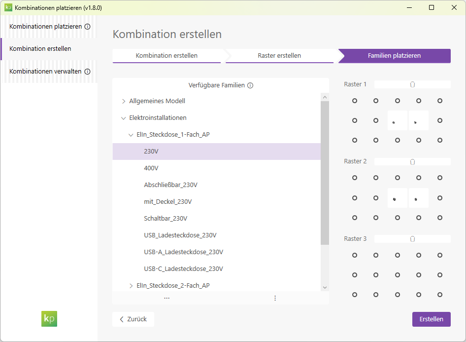
- Quick setup of combinations using drag-and-drop. The desired types are dragged with the mouse to the planned position and can then be easily moved within the grid.
When you select the "Create New Combination" option, you can start by entering a name and specifying the desired placement type for the new combination.
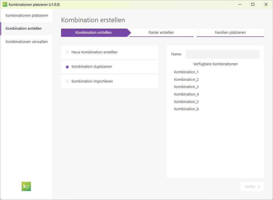
With the "Duplicate Combination" option, you can first enter a name for the new configuration and then select an existing configuration that you want to duplicate.
With the "Import Combination" option, you can first specify a name for the new configuration and then select a project file from which you want to import an existing combination.

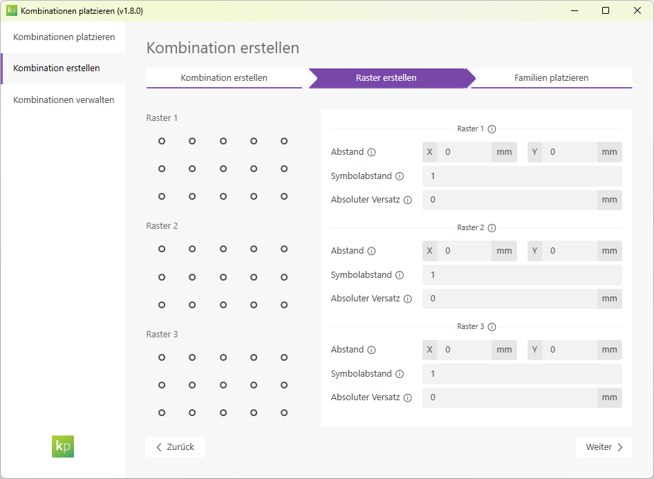
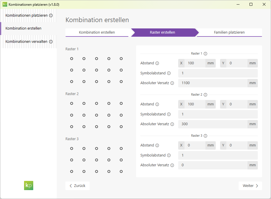
Create a grid:
Define the grids in which the families will later be arranged. Each grid offers the following settings:
- Spacing: The distance between the points where the families are to be placed.
- Symbol Spacing: Spacing between 2D symbols in the 2D views; specified as a factor.
- Absolute offset: Offset of the grid from the common, fictitious baseline. This allows you to determine the distances between the grids.
Place the combination
- Combinations can be easily selected and placed anywhere in the model as often as needed.
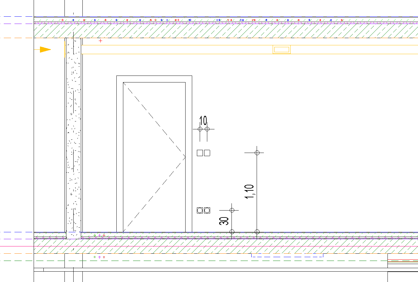
- Instance properties for the position of the symbols are set automatically. This ensures that you always get a consistent display without overlapping symbols
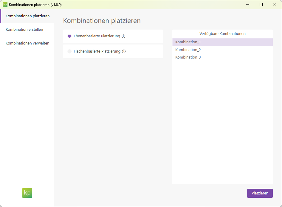
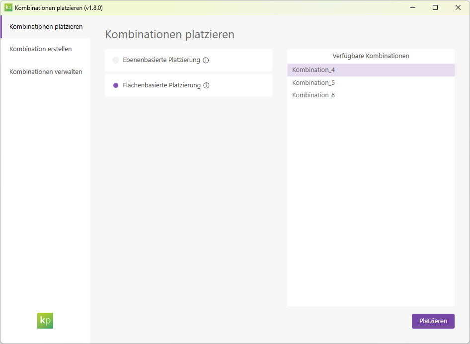
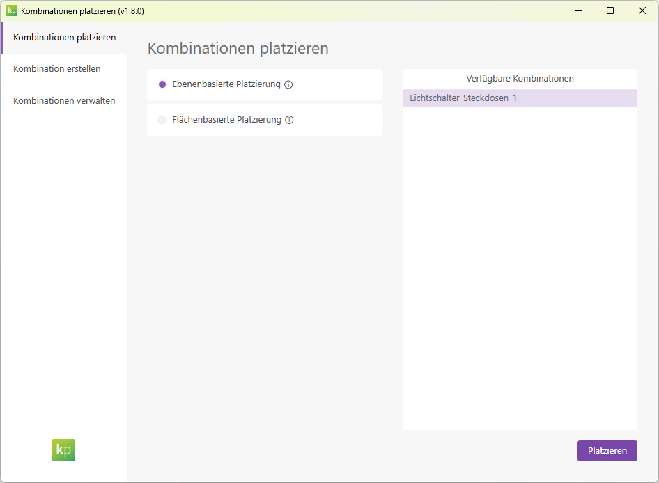
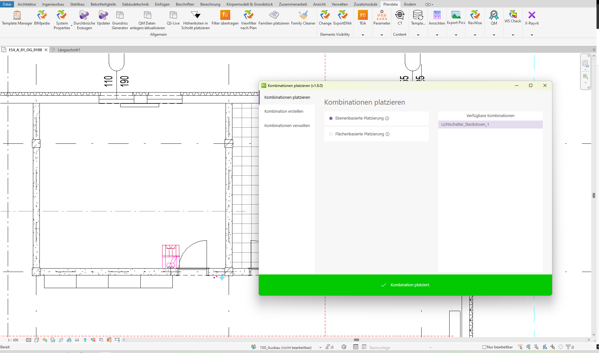
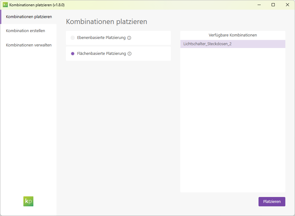
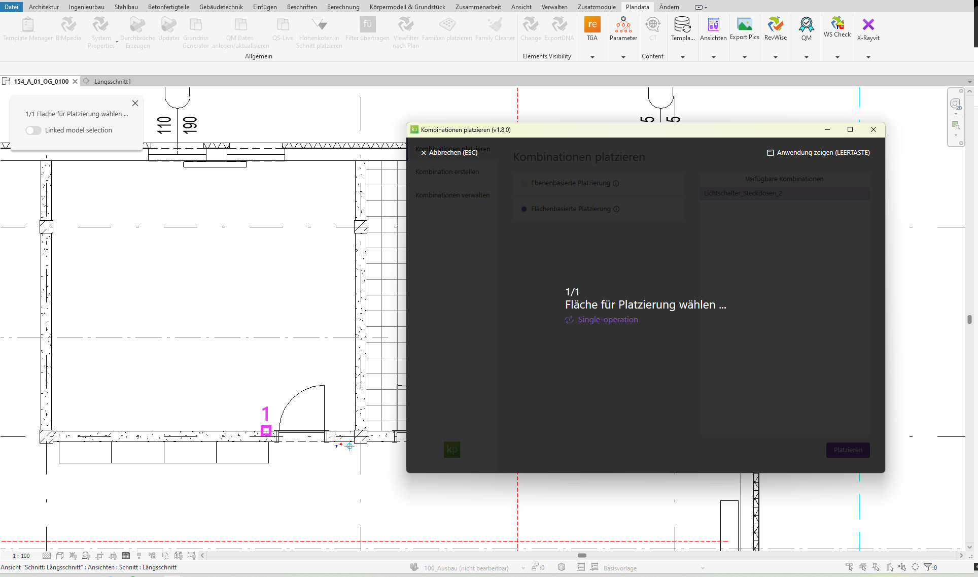
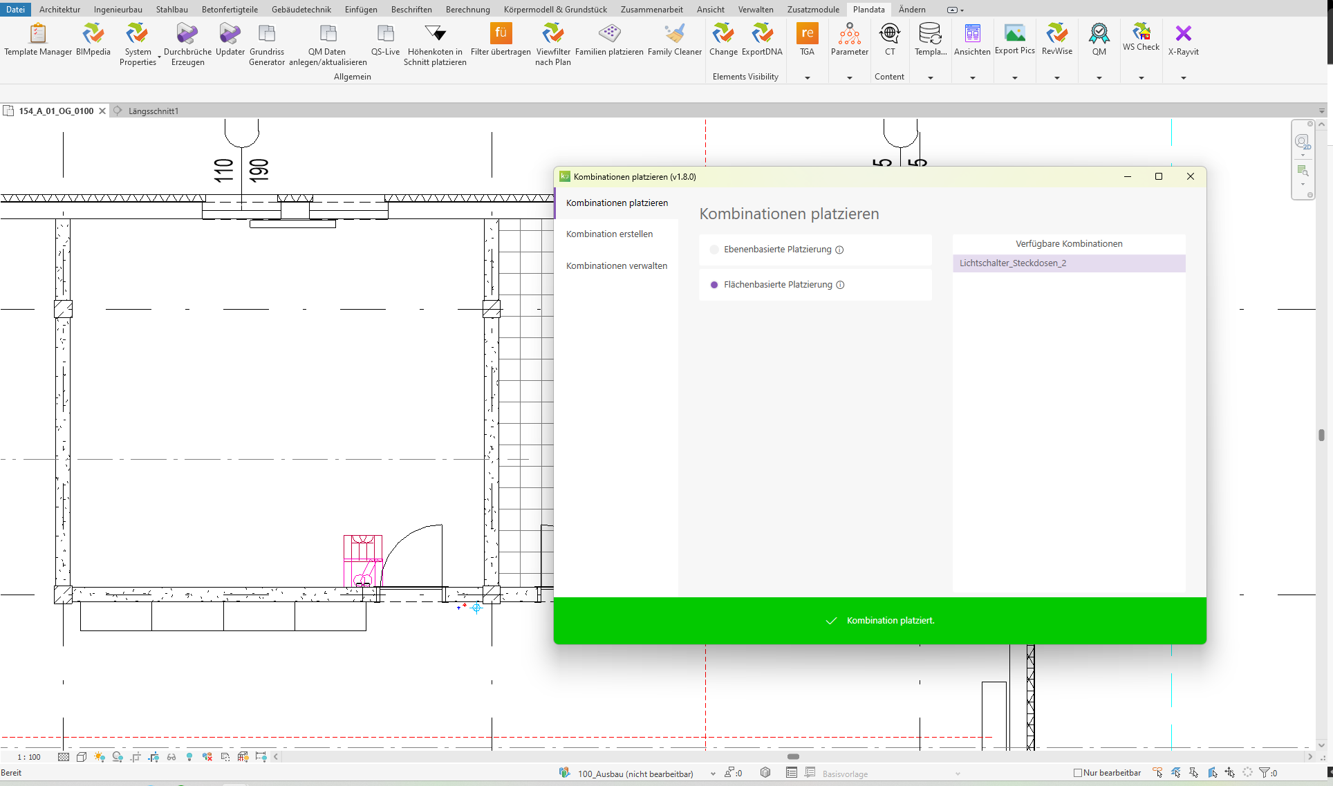
There are two placement modes available. Use the tabs to navigate through the modes and view the feature overview for each mode.
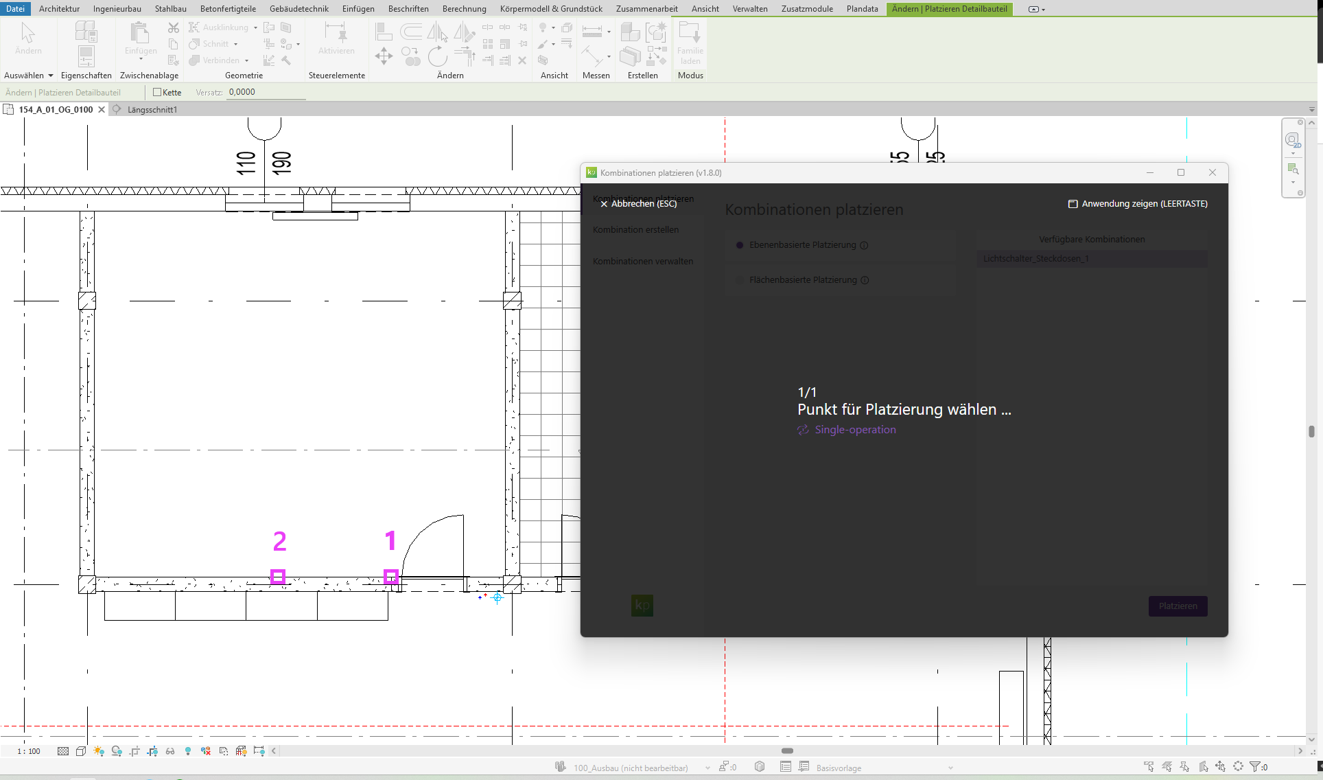
In "Layer-Based Placement" mode, placement is performed by entering two points. These points determine the placement location and the orientation of the combination. For detailed instructions, please refer to the manual.
In "Area-Based Placement" mode, placement is performed by selecting an area. For detailed instructions, refer to the manual.
Tip: You can also select elements from linked models.
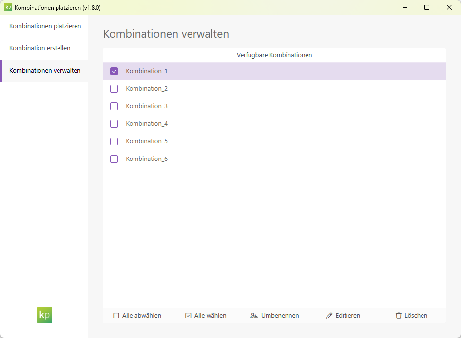
Manage combinations
Saved combinations can be renamed, edited, or deleted.
First, we create a new, floor-based group consisting of light switches and outlets.
First, we'll choose a name for our new configuration.
We define spacing and offsets for two grids.
Use drag and drop to move the desired family types to the desired grid position on the right. Click the Create button to generate the combination.
We can now choose between two placement modes:
- We are using a layer-based configuration for placement.
Note: The floor plan used has an FBOK plane as its reference plane.
- We are choosing an area-based configuration for the placement. This was created in the same way as the plane-based configuration.
Note: The floor plan used has an FBOK plane as its reference plane.
Note: Even in area-based mode, the height offsets are relative to the reference plane of the floor plan in which the combination was placed.
1.10.0.0
- Revit 2026.0 through 2026.4 is now supported.
- The info icon opens the BIMpedia article.
- Pressing the F1 key opens the BIMpedia article.
- Placed combinations are not automatically adjusted when changes are made.
- Placement of combinations is only possible in 2D views.
If you have any problems or questions, or if you have ideas or suggestions, please feel free to contact our customer service team. We look forward to hearing your suggestions for improvement!