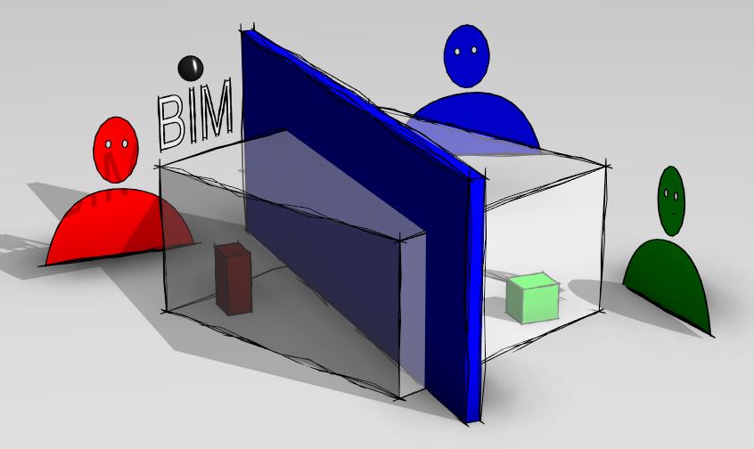
Using a central model, multiple users can work simultaneously on different parts of a project in Revit. The term is derived from the field of information technology, where it describes multiple-user access to a centrally stored Revit model. In this context, one also speaks of creating a "division of labor."
This article describes the basic benefits, setup, and day-to-day use of a central model.
In addition, the guide explains additional settings that help maintain program performance and reduce storage space.
All Revit files relevant to the project must be created as central models (central project models), as only central models allow for simultaneous editing by a multi-member project team.
All modeling guidelines require working within a central model.
Central models should primarily be created by staff members responsible for BIM and configured on a project-by-project basis.
The ideal conditions for this would be:
- A clearly named project directory accessible to all project team members. (Server or cloud)
- Project kickoff meeting to clarify the assignment, scope of work, project scope, timeline, etc.
- Some companies use a project initiation form for quality assurance. This form asks for the information most relevant to setting up the project.
The more precise the targets and information, the more effectively the central model can be configured
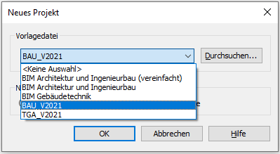
Create a new Revit file based on the appropriate template.
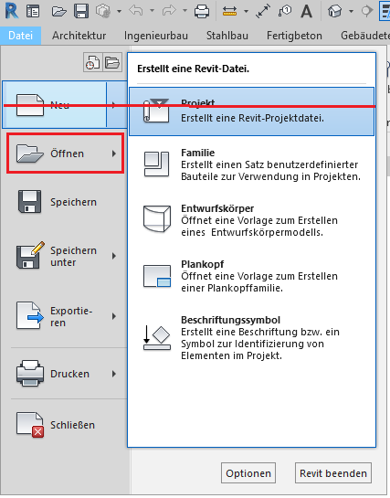
First, open a new project and select the desired template file:
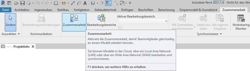
Enabling collaboration mode
The Collaboration mode is enabled in the Collaboration tab, under the Manage Collaboration group. Before you can create editing areas for the individual disciplines, you should enable the Collaboration mode in the Collaboration tab.
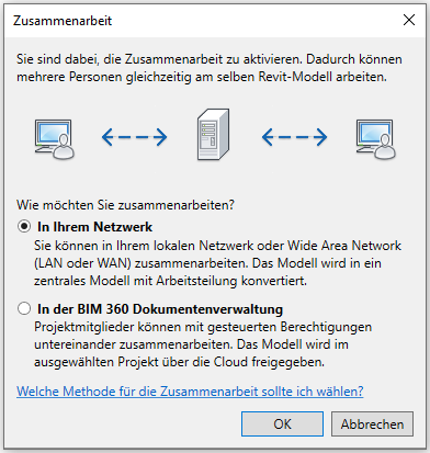
The Collaborate window will then open, prompting you to save the model so you can switch to collaboration mode.
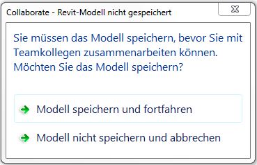
Save the project in a location that is accessible to all team members.
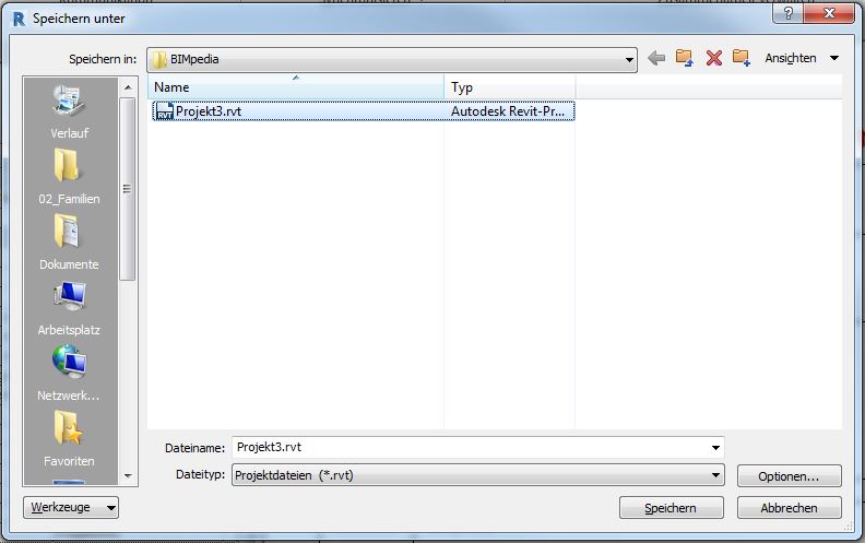
In the next step, you can specify in the window that opens whether you want to collaborate in the cloud or over the network. In this example, we’ll work over the network (select: Collaborate on your network). When you click OK, Revit will save the project.
Save
To turn the model into a functional central file, follow these steps.
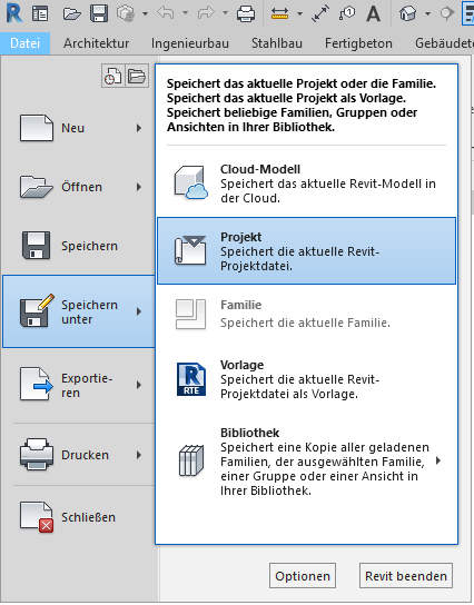
In Revit, select File > Save As > Project to open a File Explorer window:
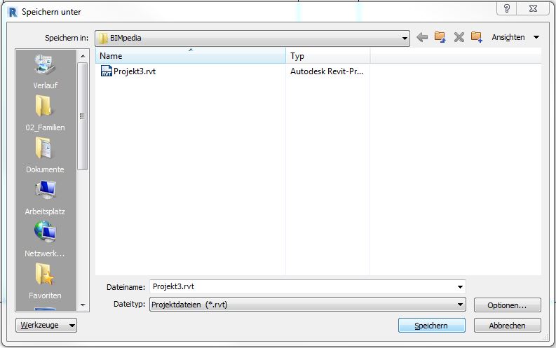
Under "Options," make the following settings:
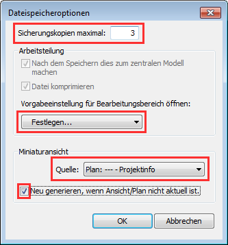
- Backup copies (recommended): 3
- Default setting for opening the editing area: Set...
- Thumbnail view -> Source: Plan: --- - Project info
- Check the box next to 'Regenerate if view/plan is not current.'
Click OK, then Save, and Revit will convert the file into a central model; the Synchronize button will now be available.

Revit has now automatically created two editing areas. You can open the Editing Areas window by double-clicking the small icon next to the editing areas.

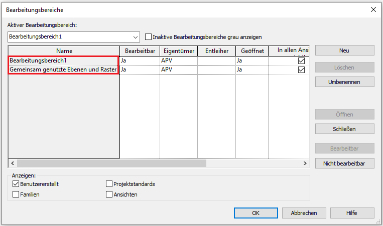
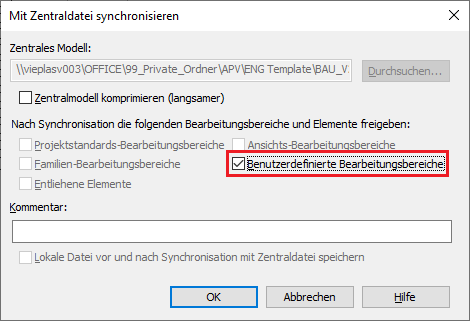
When you sync for the first time, you can now share these so that other users can work with them as well:
Creating editing areas
To make the most of the central model's features, it is recommended that you create additional editing areas.
NOTE:
Since the editing areas must be redefined each time a project-specific master file is created based on Revit templates, it is recommended to also save template files as master files in the template folder. However, with this approach, you cannot use the Revit command File -> New -> Project; instead, you must use the command File -> Open -> Project.
1. Create layers. This is done using the Level Manager (if available), or otherwise using the Layer tool. For instructions, see Autodesk Revit: Layers
2. Update the browser structure
3. Define the coordinate system,
- Project coordinate system (project datum)
- If necessary, reference to the global coordinate system (surveyor's point), (see also Positioning in the Cartesian coordinate system)
- Further information can also be found in the article Terrain: Topography
4. Create a building grid
5. Create image sections (For information on image sections, see the article "Editing Areas")
6. Country-specific settings in the CONSTRUCTION model, if Plandata families are used
Germany:
- Delete Austrian door types
- Delete Austrian labels
- Correct KSS material hatching
- Correct the material color of STB and KSS
- Adjust line weights
- Adjust dimension line weight
7. Adjust the drawing frame:
- Update the "Location" family
- Update client logo
- Insert icon / project overview (jpg)
- Legends
Germany:
- Add the parameterized North Arrow family to the A0 drawing frame
8. Set up links
9. Set up/enable the "Copy and Monitor" function for the relevant objects
Depending on the role a central file plays within a project, additional measures may be necessary.
10. If a planning management tool is used, such as Plantool, its functionality must be tested
- Test plots A0 and A3
- Check plan coding
11. Training for the person responsible for the model