This tool is designed to analyze projects and their models and provide insights into their model size, quality, number of drawings, and so on.
Quality assurance in BIM projects often involves a significant amount of manual work: warnings are ignored, models become bloated without being checked, and design changes go undetected. Without centralized analysis, it remains unclear whether a model is “healthy”—or in urgent need of revision.
- Transparent model quality across all disciplines and phases
- Early detection of critical model conditions (warnings, performance, data garbage)
- Direct integration with Revit via the Snapshot feature
- PEF system for prioritizing errors by urgency
- Central visualization of all projects on a single platform
- Reduction of support effort through standardized analysis
General
This tool reads data directly from Revit models. It exports four values from the models
- Revit's internal warnings. These do not automatically equate to errors, as some of these warnings are unavoidable. Therefore, a nuanced assessment of these issues is essential.
- The number of objects currently in the model (regardless of whether they are placed or not). Since a project with many objects is likely to generate more warnings, this number should be proportional to the file size.
- The file size, measured in bytes, provides a general indication of model maintenance. With proper model maintenance, the file size should decrease abruptly whenever maintenance measures take effect.
- The number of drawings read should provide information about the project’s status or an indication of the phase, since conceptual design produces significantly fewer drawings than construction design.
Workflow
- The "Container" tool reads the data from the Revit model
- Data is imported into the QM database
- The QM dashboard is updated
- Reports are generated and distributed
User interface
Depending on the role you've logged in with, you'll only see the projects assigned to you.
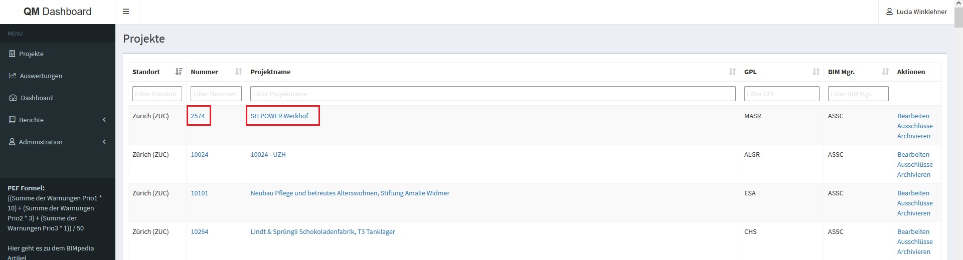
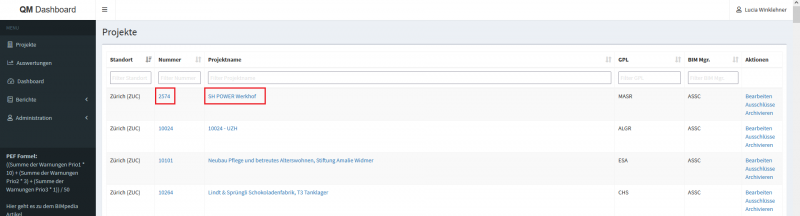
The project overview displays all projects.
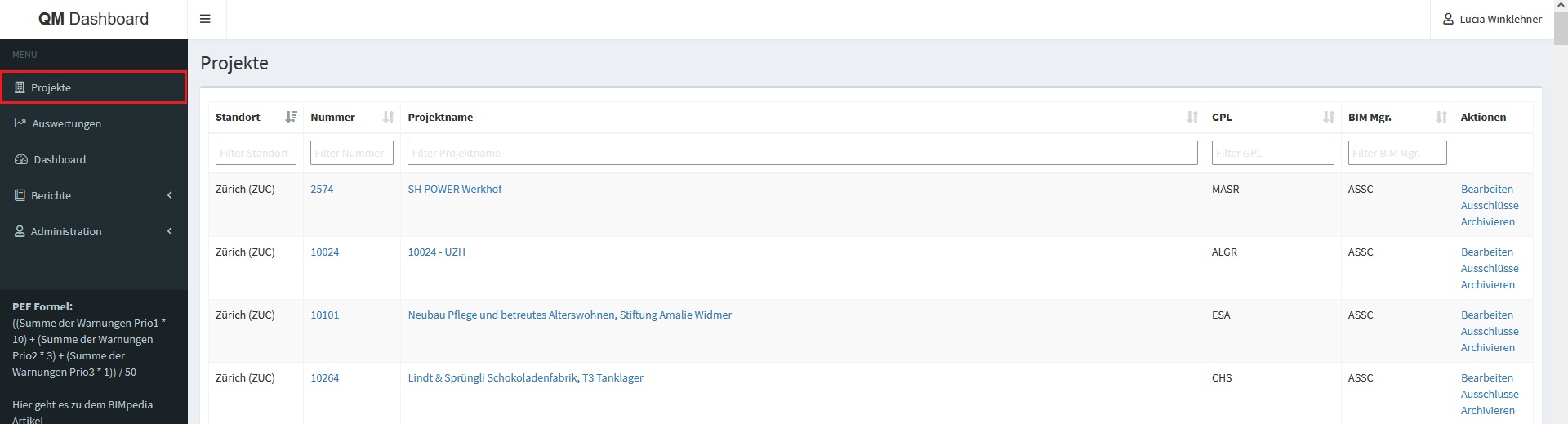
A project consists of several models. These can be viewed under "Details."
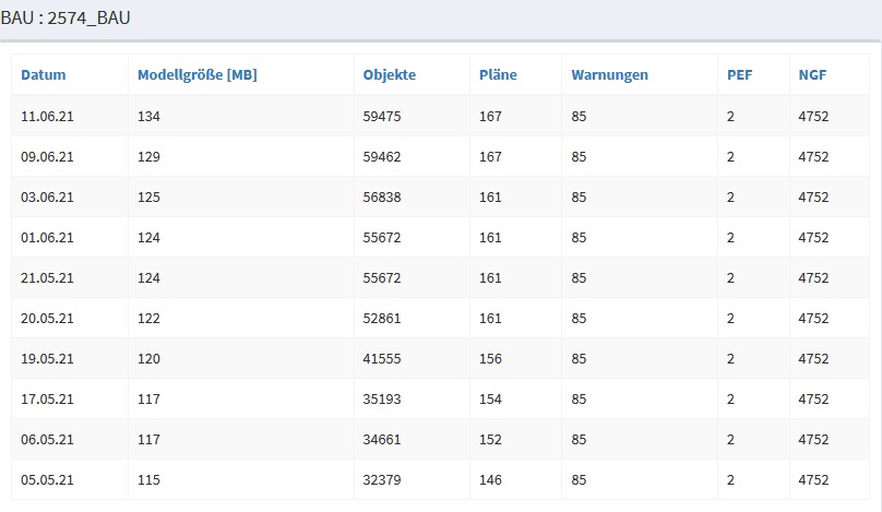
The individual models are then organized by discipline. Their "original" model names are also displayed.

Selecting a model updates the graph in the lower section or displays the graph for the selected model.
The historical data is displayed in the right-hand pane next to the graph.
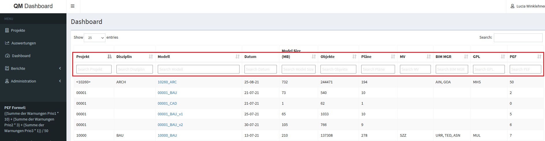
Under the "Dashboard" menu item, you can view all models assigned to the user. Here, you can sort all values as desired.
Data transmission
If a model is created in the QM Dashboard, the necessary model information is sent to the QM Dashboard every time the model is synchronized.
This process does not cause any delay in synchronization.
If a model is synchronized multiple times in a single day, the most recent version is always displayed.
Create a model
If a model is not yet included in the QM dashboard, it can be added by a qualified, designated employee.
To do this, the model must be the only one open in this Revit session.
The Revit "Send QM Data" button sends the model data to the QM dashboard.


Each model can be created only once in the QM dashboard. In this context, the model path of the central file is considered unique.
If the model was successfully transferred, the following message appears:
After taking the snapshot, the model should be synchronized once using Revit's native command.
The model should now appear in the project overview.
If this is the first model in the project, the location must also be entered. This can only be done directly in the QM Dashboard by the selected employee mentioned above.
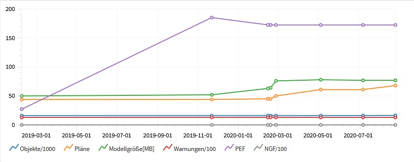
The various values have different meanings and can be interpreted in different ways. They are described in the following examples, along with an explanation of how they should be interpreted.
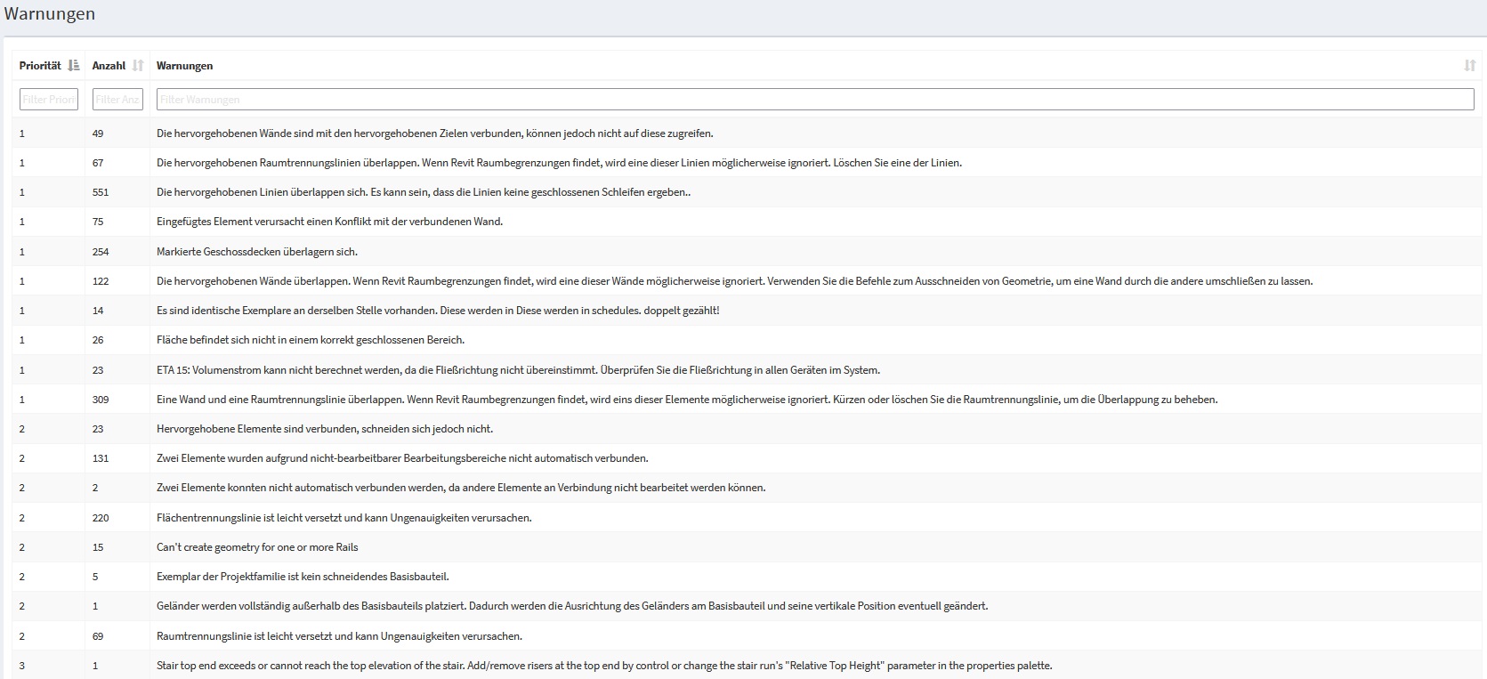
Warnings
These warnings are Revit's internal warnings. Since these are not always accurately captured in some disciplines, this is merely an indicator and not a definitive assessment. The number of warnings relative to the objects provides insight into the quality of the added objects. Ideally, these two metrics should not correlate.
Since the warnings themselves do not indicate their level of urgency, there is a metric known as PEF (Project Error Frequency)
Unkitisch:
- In the example below, the "Objects" and "Errors" values are not directly related to one another. However, as the number of objects—that is, the object density—increases in the project, the "Errors" value remains constant or even decreases slightly.
Critical:
- Case
1: If the warning value exceeds the object value, this is very concerning. This would mean that, theoretically, every object contains a warning. - Case
2: The object value increases, but the warning value rises sharply in relation to the object.
This means that the newly added objects are all error-prone and should be checked.
Warnings and Possible Solutions
Stairs:
- The top of the staircase is either higher than or lower than the height specified for the staircase. Add or remove risers at the top, or change the settings for the height of the top of the staircase in the staircase's instance properties.
SOLUTION 1: Add slopes using handles (blue circles) SOLUTION 2: Temporarily change the "Desired Number of Slopes" parameter and then change it back (Revit bug)
- The bottom of the staircase is below the base height specified for the staircase or does not reach it.
SOLUTION: Add or remove risers at the bottom, or change the base height settings in the staircase's instance properties.
- The actual number of inclines differs from the desired number.
SOLUTION: Add or remove risers using the handles (blue circles; the arrows only move the treads). Or change the desired number of risers in the staircase properties.
- The actual width of one or more flights of stairs is less than the minimum width specified for the stair type.
SOLUTION: Adjust the width using the arrow keys or change the "Minimum Width" type parameter
- The actual tread width of the staircase is less than the minimum tread width specified for this staircase type.
SOLUTION: Font settings > Adjust minimum character width or change calculation rules.
- The actual riser height of the staircase is greater than the maximum riser height defined for the staircase type.
SOLUTION: Go to Type Settings > Adjust Maximum Step Height or Change Calculation Rules.
- The thickness of the notches must not exceed the thickness of the landing.
SOLUTION: Change the notch
- The components of the staircase are not connected throughout. This may result in incorrect display and labeling.
SOLUTION: Move the components so that they touch each other
Duplicates/identical copies:
- The highlighted walls overlap. If Revit detects room boundaries, one of these walls may be ignored.
SOLUTION: Use the commands for cutting out geometry to make one wall wrap around the other. Or use the Tab key to select one of the grouped overlapping walls and remove it from the group.
- One element is completely contained within another.
SOLUTION: Move/delete the element (NOTE: Overlapping floor slabs do not trigger a warning in Revit; verification with Solibri is required!)
- The inserted element is causing a conflict with the connected wall.
SOLUTION: Move/delete element
- There are identical instances in the same location. These are counted twice in the schedules (parts lists)!
SOLUTION: Delete duplicate items.
- A wall and a room divider overlap.
SOLUTION: Correct the room boundary line
Slightly offset:
- The line in the sketch is slightly offset and may cause inaccuracies.
SOLUTION: Change the sketch line if possible; in some cases, this warning must be accepted (e.g., base boundary slightly offset)
- The line is slightly offset and may cause inaccuracies.
SOLUTION: Change the line if possible; in some cases, this warning must be accepted (e.g., the baseline is slightly offset).
- The reference plane is slightly offset and may cause inaccuracies.
SOLUTION: See the previous point
- The grid is slightly offset and may cause inaccuracies.
SOLUTION: See the previous point
- The room boundary line is slightly offset and may cause inaccuracies.
SOLUTION: See the previous point
- The wall is slightly offset and may cause inaccuracies.
SOLUTION: See the previous point
Rooms, areas, property lines:
- The area is not located within a properly enclosed area.
SOLUTION: Add area boundary lines
- Property boundaries do not form a closed loop. The area is not calculated.
SOLUTION: Add property boundaries
- Several rooms are located within the same enclosed area. The correct area and perimeter are assigned to one room, and the other rooms are marked as "Redundant Room."
SOLUTION: (Redundant = existing in multiple instances, unnecessary) You should separate the areas, delete the extra rooms, or move them to other areas.
- The room is not located in a properly enclosed area.
SOLUTION: Add room divider lines
- Spatial volumes overlap, ...
SOLUTION: Adjust the upper limit and upper offset
- Connection error due to a problem with editing rules or design options.
SOLUTION: Copy (duplicate) objects in Design Options
- Several areas are located within the same enclosed space. The correct area and perimeter are assigned to one area, and the other rooms are marked as "Redundant Area."
SOLUTION: You should separate the areas, delete the extra space, or move it to other areas.
- The part is not placed. Physical properties such as surface areas are listed as "Not placed" in the parts list.
SOLUTION: You can add or remove a room using the options bar in the Room tool. Room XX-XX is ignored in the energy analysis model.
- The highlighted face boundary lines overlap. If Revit detects face boundaries, one of these lines may be ignored.
SOLUTION: Delete one of the lines.
- A wall and a face boundary line intersect. One of the lines may be ignored when Revit determines face boundaries.
SOLUTION: Shorten or delete the face separation line to resolve the overlap.
Miscellaneous:
- The opening partially cuts through the base component. Cut in structural opening: opening cut.
SOLUTION: Do not create the frame using the command >Open >By Area; instead, use the reference plane and >Section
- The element is detached from the layer.
SOLUTION: This can only be determined through a specific analysis.
- The joint could not be created. The wall could not be cut out.
- One or more vertical rails cannot be created.
- The railing profile must contain at least one closed loop. The incorrect profile is not displayed in the profile list for the railing definition.
- The thickness of this floor slab may be slightly inaccurate because its shape has been significantly modified. The dimensions of this element in section and detail views may not accurately reflect the thickness shown in the type properties.
SOLUTION: The warning must be accepted; thickness is always measured vertically in shape-editing commands, which results in a change in thickness.
- The thickness of this roof may be slightly inaccurate, as its shape has been significantly altered. The dimensions of this element in section and detail views may not accurately reflect the thickness shown in the type properties.
SOLUTION: See the previous point
- Conditions: The slope of this handrail may not be parallel to the start and landing of the staircase.
SOLUTION: To create a parallel railing, separate the railing sketch at the ends of the landings. The requirements for wall enclosure are no longer met.
- Elements have duplicate 'ID' values.
SOLUTION: Change the ID (there cannot be more than one with the same ID)
- Elements have duplicate 'Name' values.
SOLUTION: Change the name (there must not be more than one with the same name)
- Elements have duplicate 'number' values.
SOLUTION: Change the number (there cannot be more than one with the same number)
- Geometry for one or more railings cannot be created
- The highlighted elements are connected but do not intersect.
SOLUTION: Remove the connection (generally, do not create connections between walls and floor slabs)
- The profiled wall could not be created. The sweep is not located on the correct wall.
Solution: Check the sweep parameters.
- The rectangular opening does not intersect the corresponding base component.
- The railing is not continuous. Discontinuities in the railing typically occur at transitions with acute angles. Try the following to resolve the issue: - Change the transition style in the railing's type properties, or - Modify the railing path at the transition.
- The distance between the calculation model and the physical models of the structural element is greater than the tolerance (0.1524).
SOLUTION: Move the analytical system axis within the object geometry
- Circle reference (Can only be removed by deleting the element; prevention: Do not connect floor slabs to walls)
... this section is being updated on an ongoing basis ... (or will be moved to a separate article in the medium term)
[Add new content here]
Number of properties
These are the objects (families) that exist in Revit and are also displayed in 3D.
An increase in this value is normal and desirable.
This figure, or its trend, is considered an indicator of the project's progress.
A sharp drop in this value may indicate:
Uncritical:
- The model was split, which reduced the number of objects in the model.
- The project was scaled down due to a planning decision.
Critical:
- Some objects were accidentally deleted from the model.
File size
The model size consists of the included 3D and 2D elements, plans, lists, views, and a history.
This history cannot be used, but it is stored along with the model and will slow it down over time.
Therefore, the model must be regularly cleaned up and the history "removed."
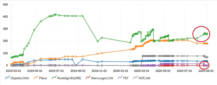
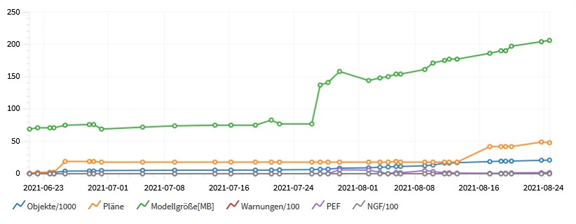
The ideal behavior of this curve is shown: a value that rises over time but exhibits regular downward trends.
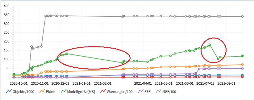
These downward trends indicate the times when the models were properly maintained.
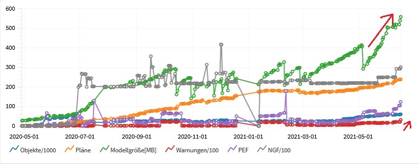
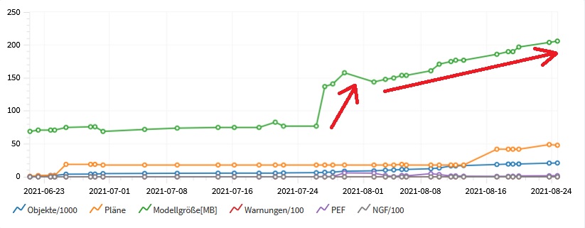
If the curve is only growing steadily, the model is not maintained.
Critical:
- Drops in performance affect the entire planning team and result in additional costs and effort at every stage of the process.
Estimated number
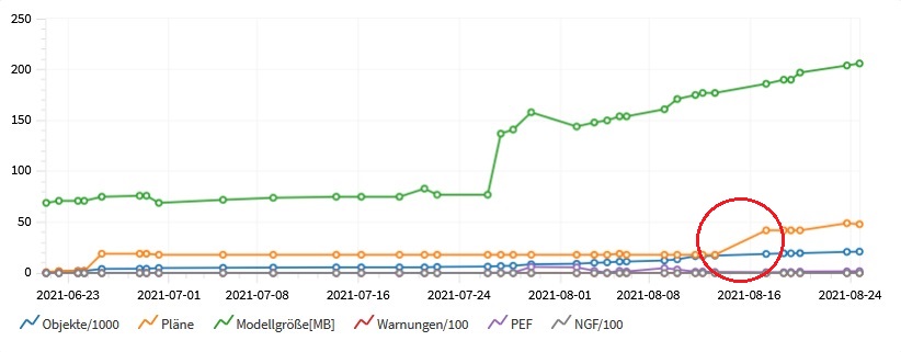
The number of plans generally increases steadily. After a phase is completed, this number may decrease. This applies only to models for which plans are actually created, i.e., architectural and building services engineering (BAU/TGA). There will be no change in this regard for so-called CAD models.
Plans from the completed phase that are no longer needed can be deleted (depending on the project).
As a rule, this curve rises sharply during the execution phase.
Critical:
- If the curve drops sharply and no phase has been completed yet, this should be investigated.
PEF
These are errors that have been assigned different weights; they have been divided into three priority levels and multiplied by a relative factor so that their relationship to the other values can be represented graphically.
- Priority 1: Alphanumeric and graphic consistency
- Priority 2: Alphanumeric consistency
- Priority 3: Graphic consistency
Different factors are assigned to these priorities. The more critical the priority, the higher the factor. These factors are then multiplied by the number of errors that occurred for that priority. Finally, this sum is divided by the relation factor.
For each model, there is also a list of warnings and their priority
The PEF value should always be considered in relation to the object error values.
Uncritical:
- If the warning value increases, the PEF value will inevitably increase as well. If there is a sudden increase in these two values, it is expected that the object value will behave similarly. This should be considered relatively uncritical, as an increasing number of objects inevitably leads to a certain number of warnings.
Critical:
- If the PEF and warning values are not proportional to the object value, this must be classified as critical, since only these new objects are causing the disproportionate increase.
1.6.0.0
- Revit versions 2026.0 through 2026.4 are now supported.
- The Revit tooltip has been expanded to provide a comprehensive description of the button's function.
- Pressing the F1 key opens the BIMpedia article (tooltip).
Unfortunately, this content is available only to our Pro users.
If you'd like to read the full article, try the Pro account or become a Pro user.