
The add-in lets you create spot elevations and dimension strings in section views.
It also provides a function for aligning existing spot elevations.
To load this content, you need to allow the YouTube service.
Placing spot elevations manually in Revit is prone to errors and takes time, especially in section views that show an entire building with many storeys. Aligning overlapping spot elevations and adding dimension strings manually takes additional time and effort.
- Automatic placement of spot elevations and dimension strings, including across multiple storeys
- Placement on the correct Revit elements
- Automatic offset of overlapping spot elevations
- A wide range of configuration options
- Support for all major Revit categories in section views
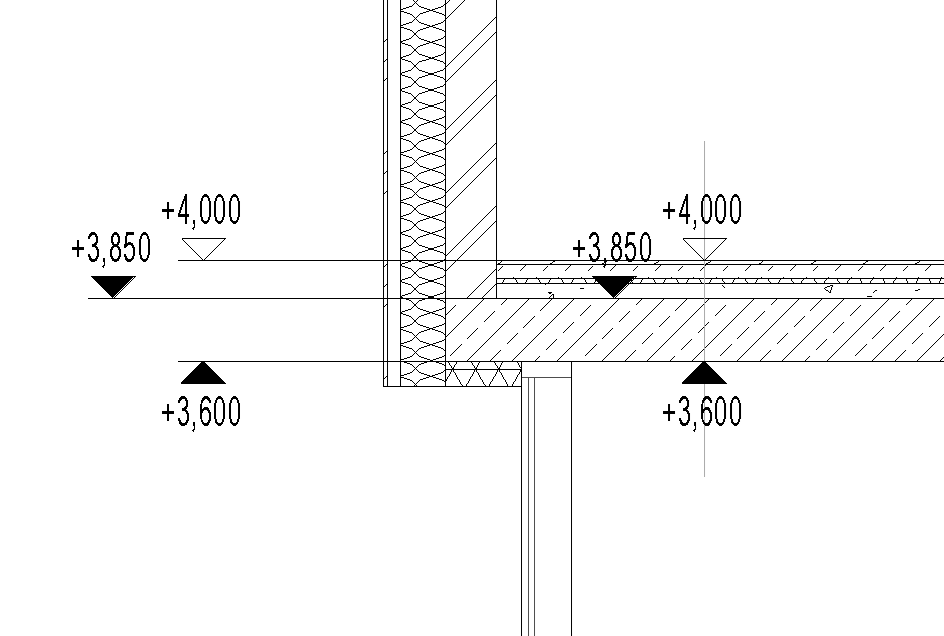
The tool places spot elevations and dimension strings where Revit elements intersect detail lines or reference planes. It only considers elements cut by the section from the following categories:
- Structural Foundations
- Floors
- Walls
- Ceilings
- Roofs
- Stair Landings
- Structural Framing
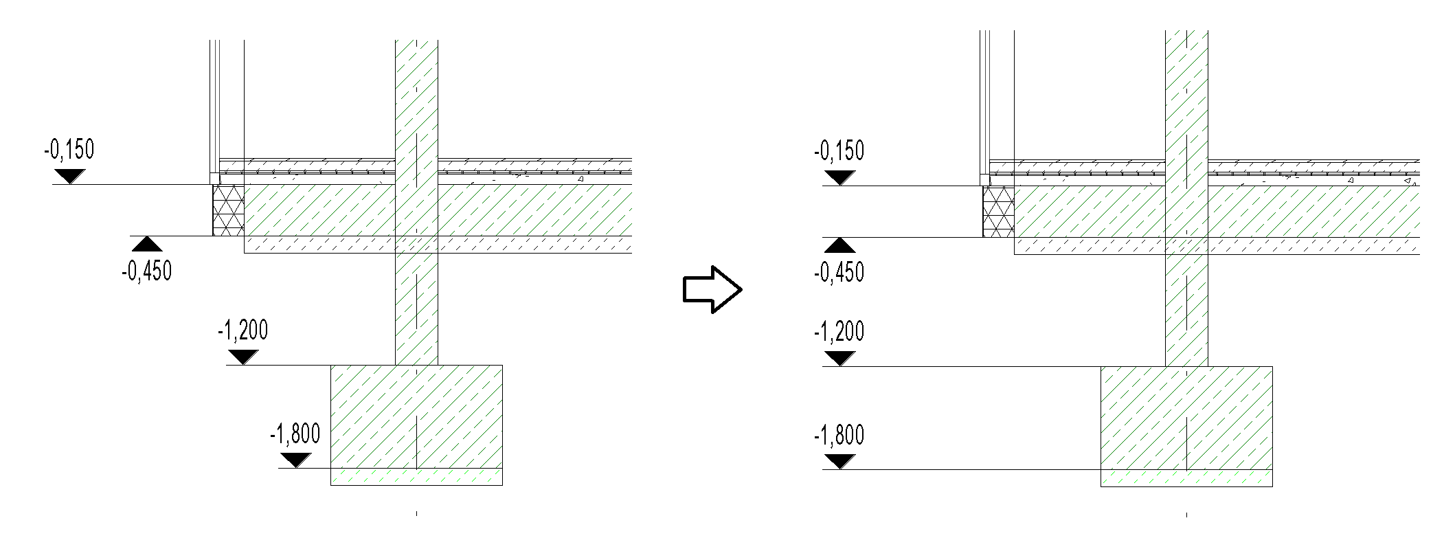
The following example shows placement with an offset (left) and without an offset (right).
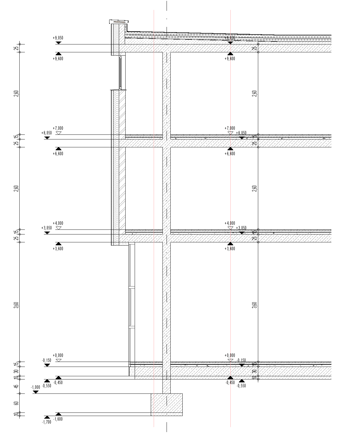
Overlapping spot elevations are automatically offset. Detail lines and reference planes are deleted after the spot elevations have been placed.
Note: Sloped surfaces are ignored during placement.
The additional alignment function (Ausrichten) lets you align existing spot elevations along a line.
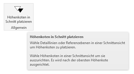
Click the Höhenkoten im Schnitt platzieren button to open the add-in.
A brief description of the functions is available in the add-in's tooltip.
Configuration
The add-in provides a user interface with several configuration options.
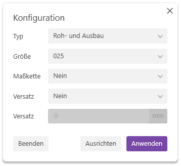
Type (Typ): Specifies whether to create spot elevations for the structural shell (Rohbau) and/or finishes (Ausbau).
Size (Größe): Sets the size of the spot elevation.
Dimension string (Maßkette): Specifies whether to create a dimension string. The standalone option (Alleinstehend) places dimension strings only, with no spot elevations.
Offset (Versatz):
The no-offset option (Nein) places spot elevations without a custom offset. Overlapping spot elevations are automatically offset to the right.
Note: With this setting, spot elevations are created without leaders.
The left (Links) and right (Rechts) options allow you to specify a custom offset.
Note: When you enter a custom offset, spot elevations are always created with leaders. Overlapping spot elevations are automatically offset in the selected direction.
Tip: Selecting the left option (Links) without entering a custom offset automatically offsets overlapping spot elevations to the left.
The following example compares the left option (Links) without an offset (0 mm) and with an offset (2000 mm). The line selected for placement is shown in grey.
Placement
Select detail lines or reference planes in a section view.
Then click Anwenden (apply) to start placing the annotations.
The spot elevations are placed according to your settings. Detail lines and reference planes are deleted after the spot elevations have been placed.
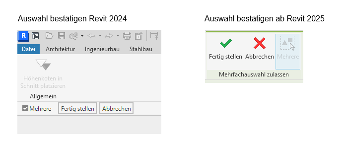
Note: If you click Anwenden (apply) without first selecting a detail line or reference plane, Revit enters selection mode. You can then select detail lines and reference planes. To leave this selection mode, you must select Fertig stellen (finish) or Abbrechen (cancel). Selecting detail lines and reference planes in advance therefore makes the workflow more efficient.
Alignment
Select existing spot elevations to align them along a line. The uppermost spot elevation always serves as the reference. This function is available both through the tool button and through the Ausrichten (align) button.
Tip: Assign a keyboard shortcut to the add-in in Revit. You can then select spot elevations and use the shortcut to align them automatically, without opening the add-in.
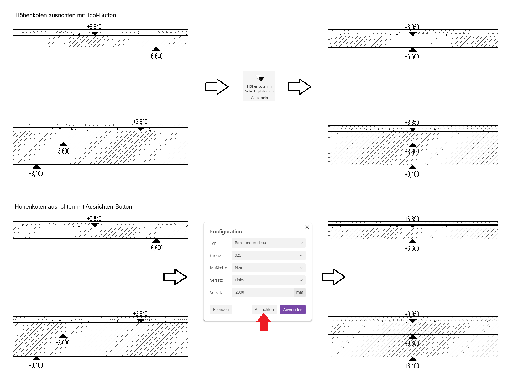
Spot elevations with leaders can also be aligned.
1.8.0.0
- Revit 2026.0 through 2026.4 is now supported.
- The info icon opens the BIMpedia article.
- Pressing F1 opens the BIMpedia article.
The add-in is designed to work with Plandata's Revit Pro Content.
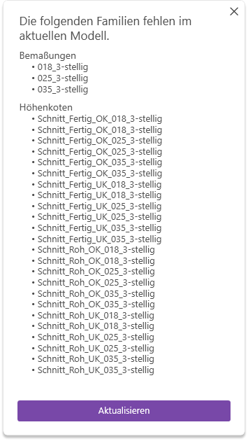
The following spot elevation and dimension types must be present in the model. If any of these types are missing, a message appears. Load the required types into the model, then click Aktualisieren (refresh) or restart the add-in to continue.
If you have any problems, questions, ideas or suggestions, please contact our customer service team. We welcome your suggestions for improvement!
Unfortunately, this content is available only to our Pro users.
If you'd like to read the full article, try the Pro account or become a Pro user.