Ventilation units typically consist of several components and alter the properties of the air, such as temperature and humidity. They play a key role in supplying air for a wide variety of room uses.
The ventilation unit is not shown in this design phase.
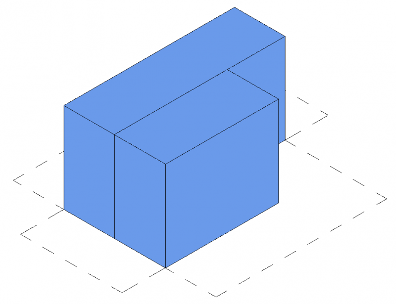
In this phase, ventilation units are represented abstractly.
Presentation
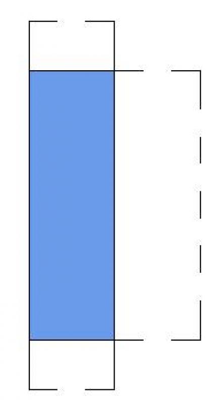
Plan view
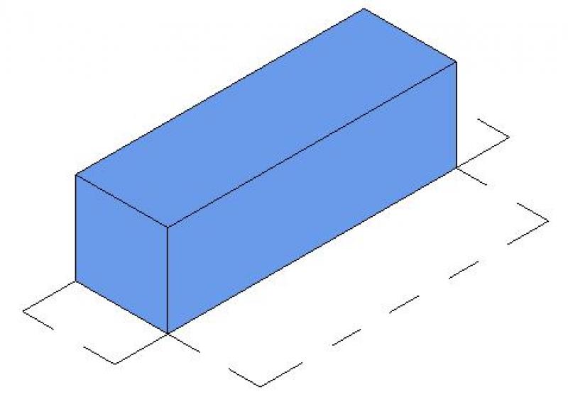
Model representation
Features
The following characteristics are defined in this phase:
- Dimensions (length, width, height of the units)
- Dimensions of the maintenance area
- Name of the system
Labeling
At this stage, the component is not yet labeled or dimensioned in the plan views.
Instructions
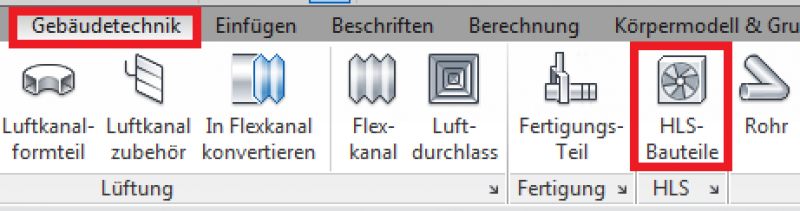
Create:
The "Building Services" tab contains the button for inserting HVAC components. The family is placed on a single plane and can then be moved manually within the section or by entering an offset in the Properties window.
During this phase of the design process, the component is supplemented with geometric data, technical specifications, and structural engineering information.
Presentation
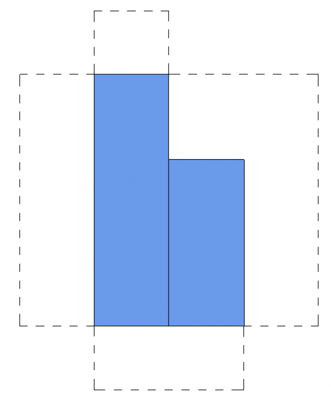
Plan view
Model representation
Features
The following characteristics are defined in this phase:
- Airflow rates
- Assignment of system types
- Information on third-party systems (e.g., loads for structural design, interface with the heating system, electrical power consumption, etc.)
- Numbering of devices (component number or sequential number)
- Detailed design of the units
- Zone units or split units must be added (=Add HVAC families)
The parameters listed above are entirely sufficient for this phase.
Labeling
During this phase, the component is marked for the first time.
- Name
- Description
Ideally, device labeling should be handled by a family that extracts the necessary information from the device's parameters and characteristics.
Instructions
A device can be modeled using a placeholder family that already exists from the preliminary planning phase. The family can be duplicated for the design. The prerequisite for this is that the family’s geometry is editable enough to achieve the required level of design detail. The type name is used for the assignment or identification of the system device.
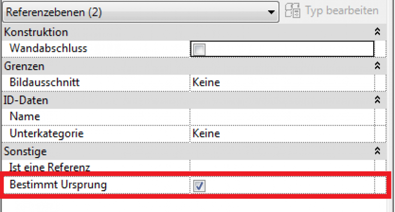
However, if the device is replaced with one from a different family, it is important to ensure that the insertion points are identical.
Note: To do this, compare the family to be replaced with the currently placed family. In both families, the reference planes must be aligned so that they match in the "Defined Origin: Enabled" parameter.
During this phase, the drawings and models of the HLS components remain unchanged from those created during the design phase.
Presentation
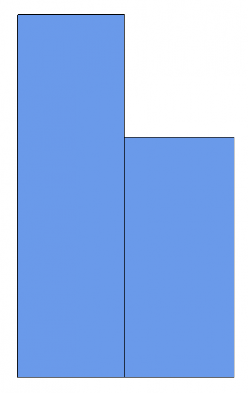
Plan view
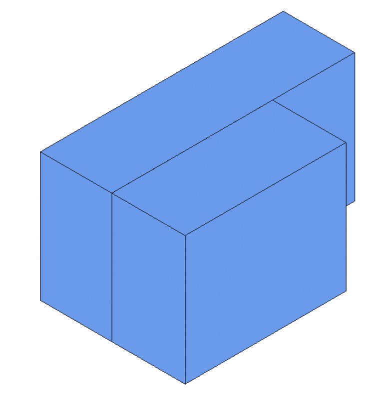
Model representation
Features
The following characteristics are defined in this phase:
- External pressure drop according to the pressure drop calculation
- Heating capacity/pressure drop of the units for the piping network calculation
- Cooling capacity/pressure drop of the units for the piping network calculation
Labeling
Instructions
At this stage, no additions are needed to the labeling already included in the draft.

Unfortunately, this content is available only to our Pro users.
If you'd like to read the full article, try the Pro account or become a Pro user.