This Revit add-in allows you to automatically place openings based on configurable rules.
To load this content, you need to allow the YouTube service.
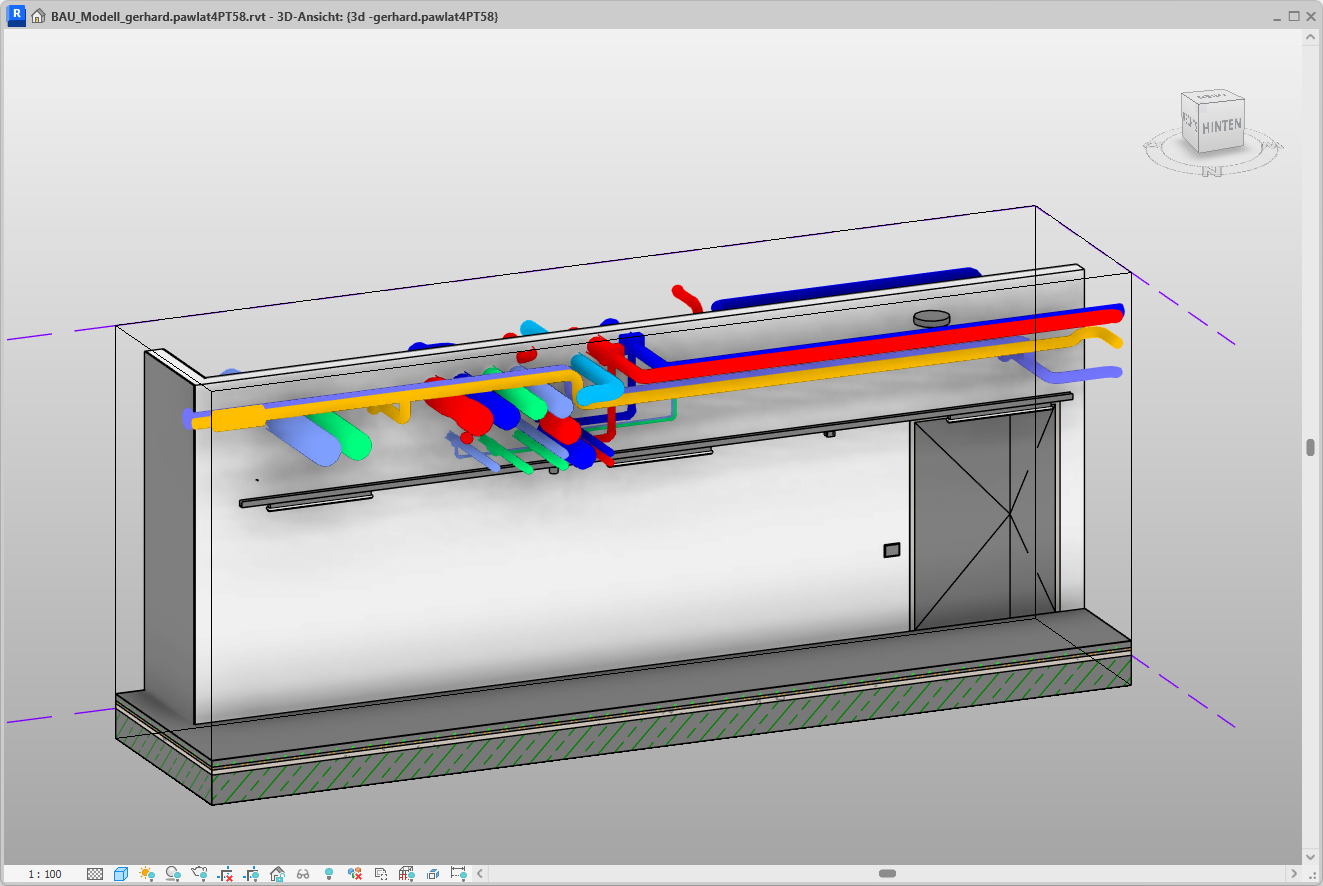
Once a building services model has been received, a large number of penetrations must be created. For larger projects, this can quickly run into the thousands. Depending on the penetrated component (e.g., a reinforced concrete fire wall) and the penetrating component (e.g., a cable tray), different requirements must be met. This process is time-consuming and ties up valuable resources.

- Collisions between elements of the technical routing (pipes, ventilation ducts, cable trays, etc.) and structural elements (floor slabs, walls, etc.) are automatically detected.
- Automatic placement of openings according to flexibly definable rules.
- All relevant parameter values are filled in.
- A detailed results report provides an overview of the placed openings.
- Automatically generated 2D and 3D views allow for optimal inspection of the openings.
This Revit add-in offers extensive configuration and placement options through an incredibly easy-to-use interface.
The optional parameter updater ensures that cutouts are automatically updated whenever changes are made.
Making breakthroughs
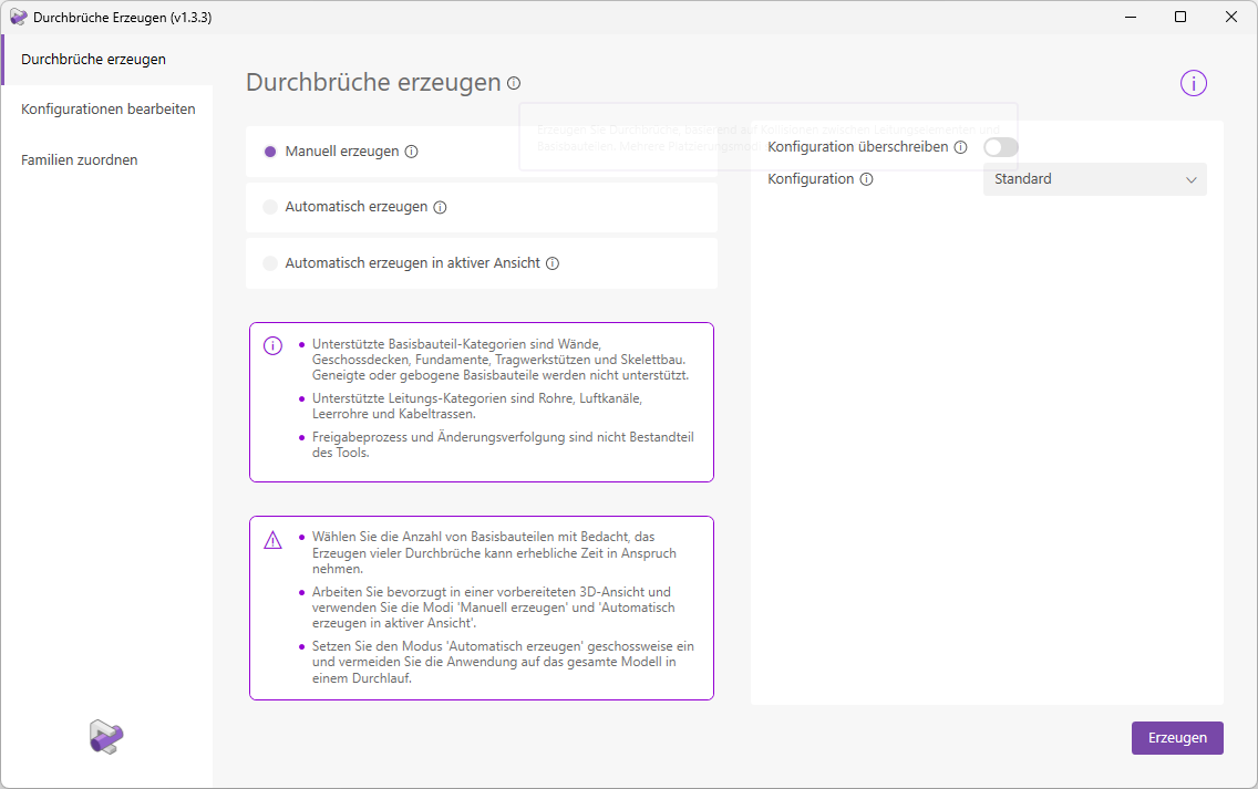
There are 3 placement modes available for creating cutouts:
Manually select base components and cable elements in a view. The collisions of the selected elements are analyzed sequentially, and cutouts are placed at all permissible intersection points. The selection can be made in both 3D and 2D views.
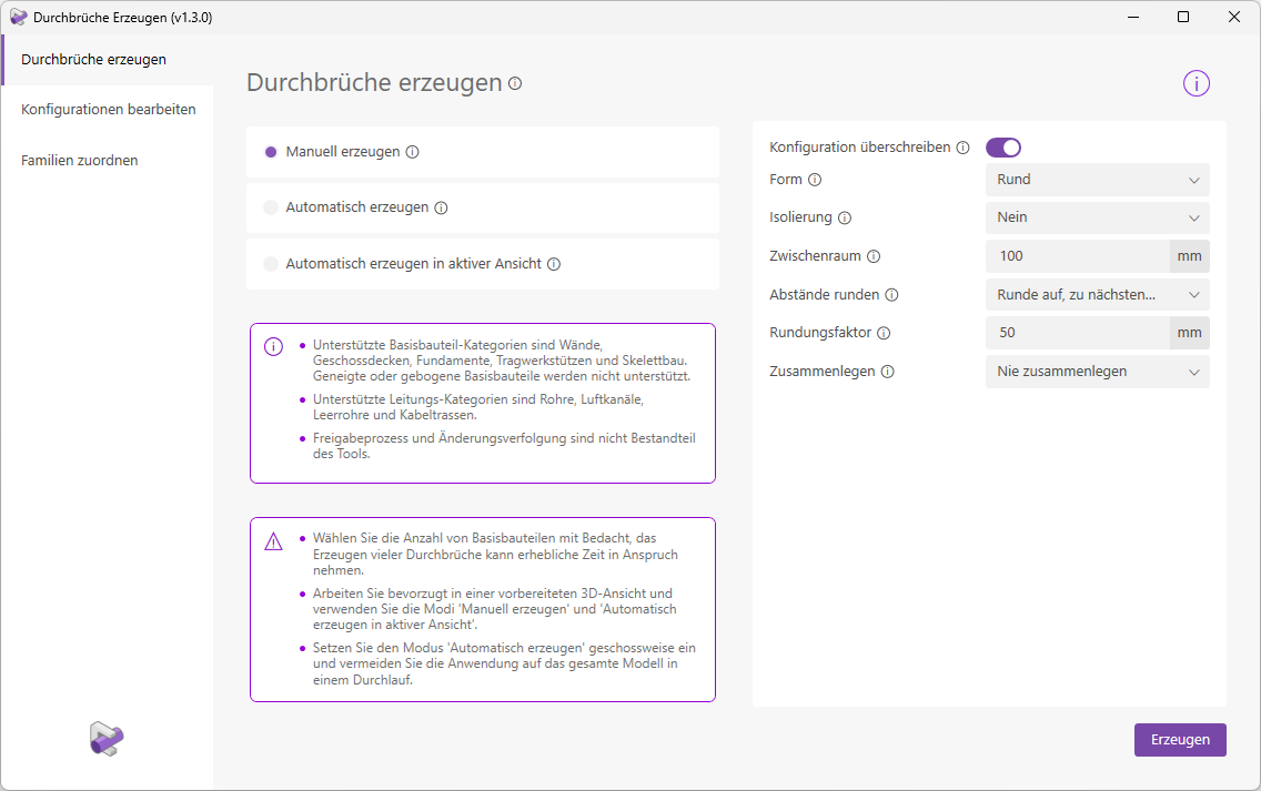
Optionally, you can temporarily override the configuration in this placement mode. This allows you, for example, to easily change the cutout shape for the next placement from “Rectangular” to “Round” without having to switch to the configuration settings to make the corresponding adjustments there.
During automatic generation, the model is analyzed according to the predefined settings (models, layers, components, etc.), and openings are placed at all permissible intersection points.
In this mode, the base components and line elements for the collision check are selected based on the active 3D view. All visible elements within the 3D section area are taken into account.
The unique feature of this mode is that you can start creating openings immediately without having to configure any settings first. However, you also have the option to further restrict the selection using the placement settings (e.g., consider only base component walls).

Edit configuration
The "Edit Configuration" menu item first takes you to the configuration overview.
Here, you can create, duplicate, rename, and delete configurations. You can also import and export configurations to share them between projects.
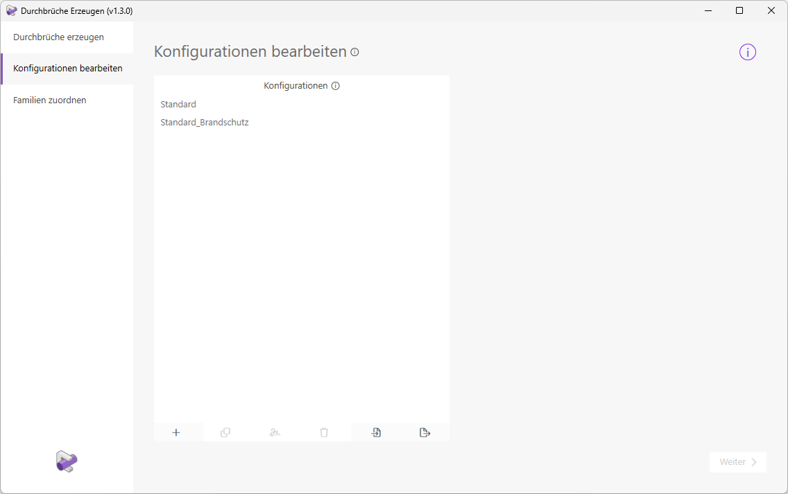
Note: The "Standard" and "Standard_Fire_Protection" configurations are already available, so you can start creating openings right away. These two configurations cannot be deleted or renamed.
Select a configuration and click the 'Next' button to proceed to the settings.
Here, you can configure settings for each line type or line system individually, or for an entire category (e.g., cable trays).
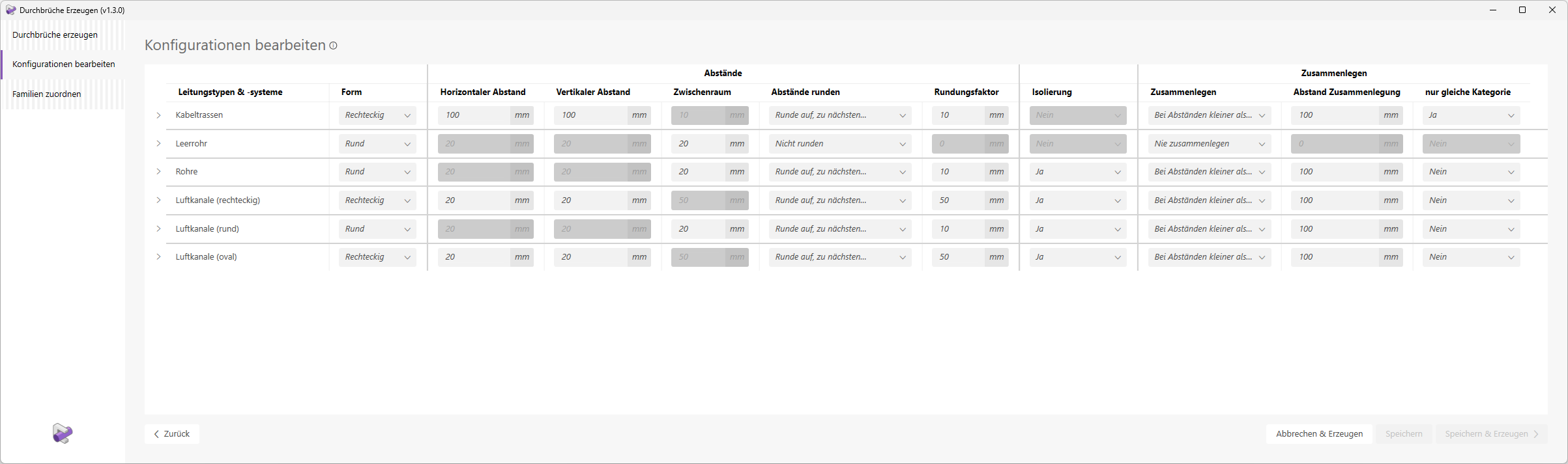
The following settings are available
- Shape:
Determines the shape of the cutout family to be used. - Horizontal/Vertical Distance:
Determines the distance between the line element and the base component for a rectangular shape.
Determines the distance between the conductor element and the base component for round shapes.
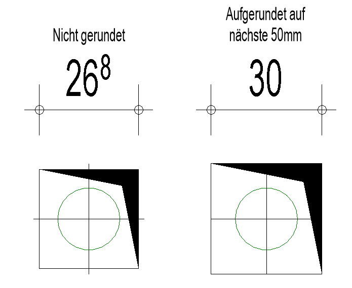
Round the dimensions of the cutout up or down as needed.
The following example shows rounding based on a rounding factor of 50 mm.
Determines whether the conductor element or the insulation is the determining factor for the breakdown voltage.
Determines whether individual breakthroughs should be merged into a single, larger breakthrough.
Optional spacing for merging cutouts.
Allows you to merge line elements only with line elements of the same category, e.g., merge cable routes exclusively with other cable routes.
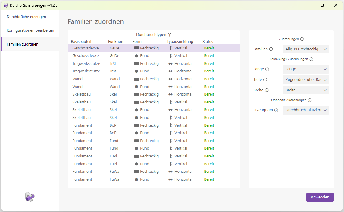
Assign families
The assignment of cutout families to the corresponding base components is fully automated.
Simply load the relevant families into your Revit project and then open the Revit add-in "Generate Openings." The parameter values for the dimensions of the openings are also assigned automatically. The "Created on" text parameter is used to store both the creator’s username and the corresponding placement date in the opening instance. This parameter is also assigned automatically.
Automatic assignment applies exclusively to the following families of Plandata content:
- Allg_WD_rectangular
- General_WD_round
- Gen_BD_rectangular
- General_BD_round
- General_DB_Area_Rectangular_Top
- General_DB_Surface_Round_Top
- General_DB_Surface_Rectangular_Side
- General_DB_Surface_Round_Side
In addition, you have the option to manually assign additional families.
Note on supported families:
If assigning a family fails (the status shows "Missing") even though the family is present in the model, it means you are using an outdated version of the family. The Revit add-in "Generate Openings" has been optimized for use with the latest families from Plandata Content; please use this in your project.
If you would like to update outdated families in your project, please discuss this with your BIM manager and contact our customer service team if necessary.
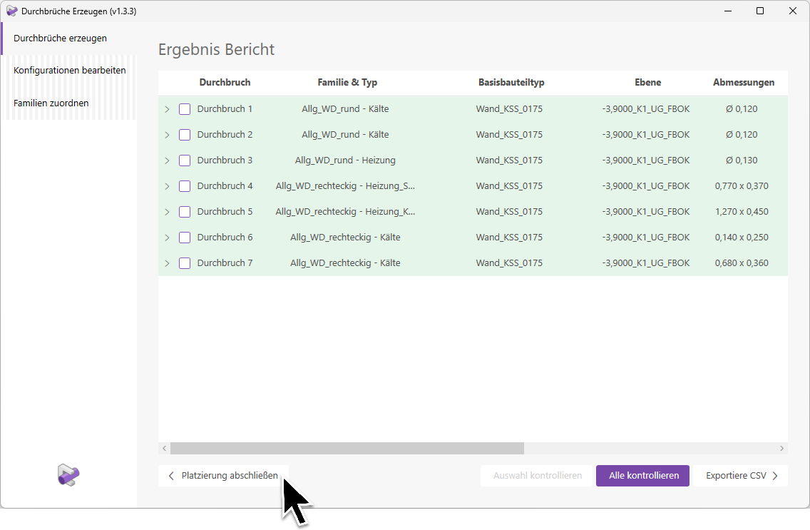
Earnings Report
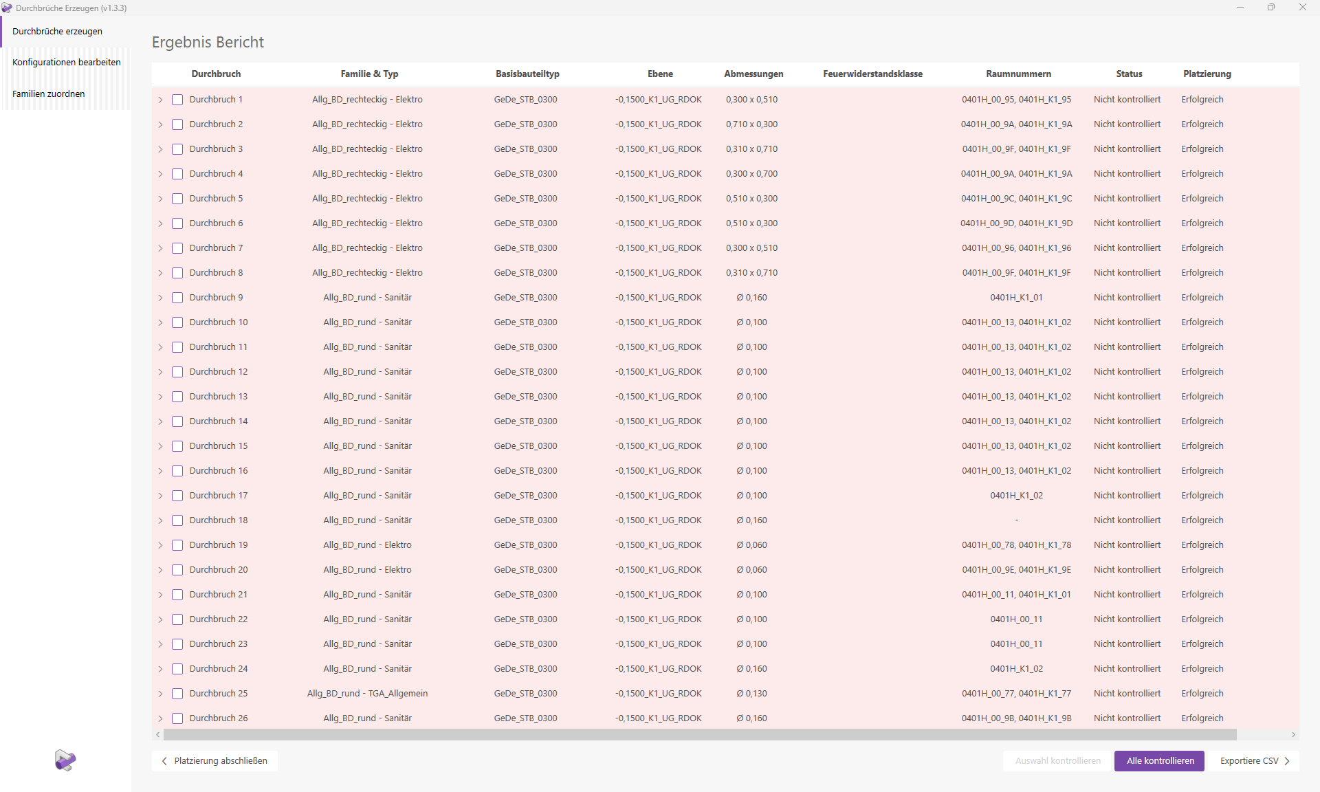
After the cutouts are created, a detailed results report is generated.
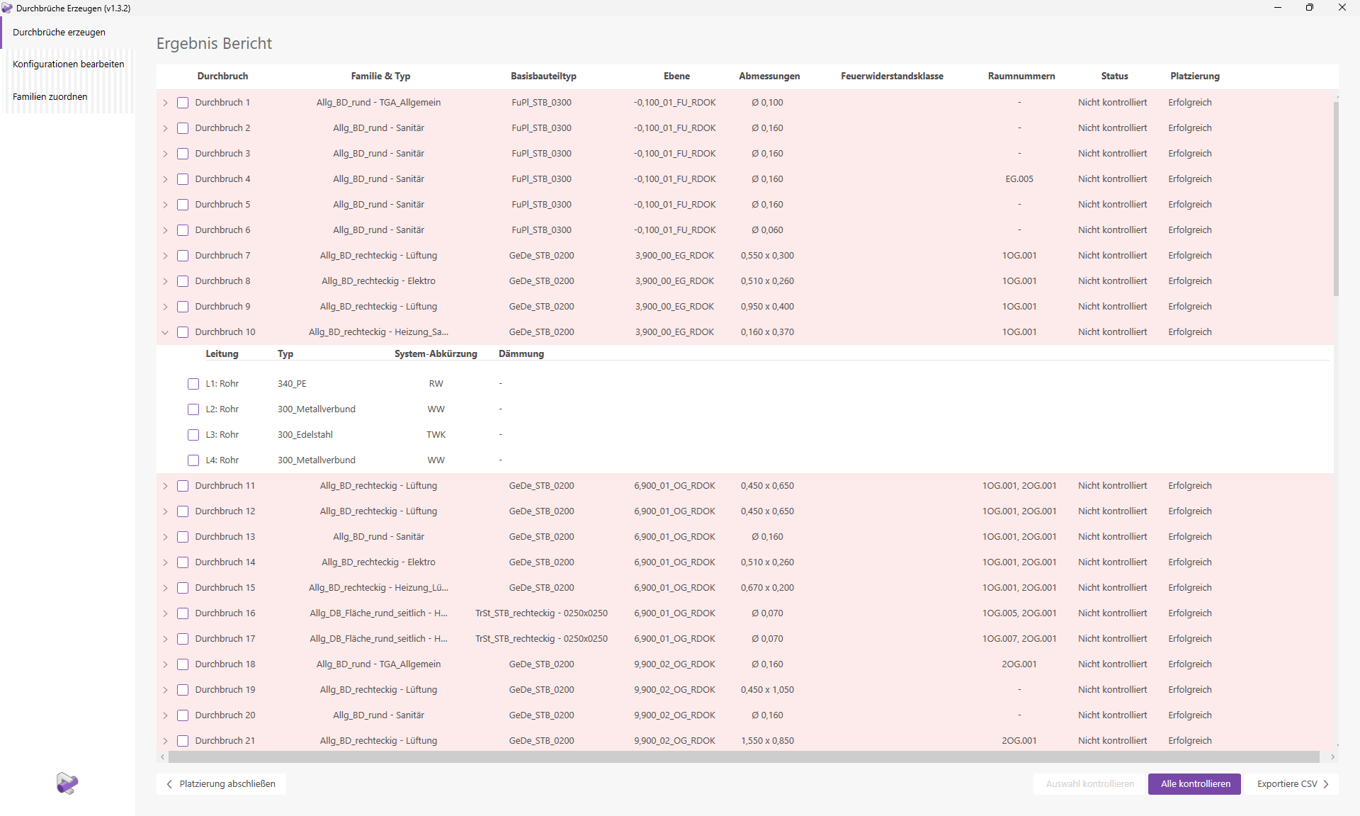
This report contains the following information:
- Cutouts
To make the review process easier for you, the cutouts are listed in sequential order. Cutouts that could not be placed successfully are displayed at the end of the report and are marked with the letter "F" for "Failure." - Family & Type
This column shows you both the placed cutout family and the family type.
Note: In the 'Family Types' section, you can learn how automatic type assignment works. - Base Part Type
The family type of the base part. - Plane
The reference plane of the cutout.
Note: In the "Cutout Properties" section, you can learn how plane assignment works. - Dimensions
Depending on the opening type, displays dimensions such as diameter, height, width, and length.
The depth (corresponding to the base part depth) is not displayed. - Fire Resistance Class
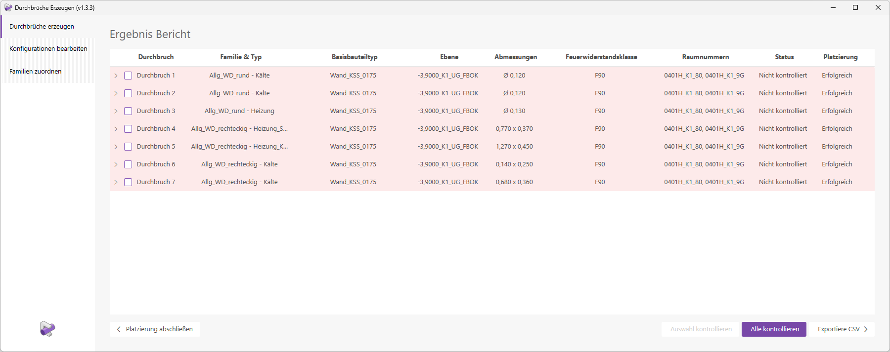
The fire resistance class of the base component - Room Number
Displays the room numbers of the rooms adjacent to the opening. - Status
Displays the current verification status of the opening. This is also indicated by the color of the entire row.
Note: Only openings with the status "Checked" (= Green) remain in the model after placement is complete. Openings with the status "Not Checked" (= Red) are removed from the model. - Placement
Shows whether the placement was "Successful" or if errors occurred. You can find more information on this topic in the "Errors and Warnings" section.
You can expand each indented line to view information about the line elements that generated it.
- Piping
: Piping elements are listed by serial number. The piping category is also displayed. Example: 'L1: Pipe' - Type
The family type of the line element. - System Abbreviation
The abbreviation of the piping system. - Insulation
Specifies the type of insulation, if any.
Export CSV
The "Export CSV" button located below the results report allows you to save the results report as a text file.
Note: The text file contains a variety of additional information, such as element IDs, system name, etc.
Parameter Updater
The Parameter Updater keeps the elevation parameters of openings up to date at all times.
As a result, the labels for openings always display the correct elevation values. This means that manually entering and updating these parameter values is now a thing of the past. It is a "Dynamic Model Updater."
To load this content, you need to allow the YouTube service.
If openings are added or modified (e.g., moved) in the model, some parameters are automatically updated.
The following families and parameters will be updated:
- Allg_WD_rectangular (Plane height above 00, Plane height, Bottom edge above plane)
- Allg_WD_round (Plane height above 00, height of plane, axis above plane)
- Allg_DB_Area_Rectangular_Top (Depth*)
- Allg_DB_Surface_Rectangular_Side (Plane height above 00, axis above plane, depth*)
- Allg_DB_Surface_Round_Top (Depth*)
- Allg_DB_Surface_Round_Side (Plane height above 00, axis above plane, depth*)
*The depth of the base component "Beam" is updated only for "Skel_STB".
Note 1: Cutouts that were not created using "Create Cutouts" will also be updated.
Note 2: Only the modified breakthrough instances are updated; not all instances in the model.
Let’s take a closer look at how the parameter values are calculated:
- General_WD_rectangular:
- "Layer height above 00" = Height of the linked layer
- "UK above level" = "UK above level" + "Height of level"
- "Height of layer" = 0.0
- Allg_WD_round:
- "Plane height above 00" = Height of the linked plane
- "Axis above level" = "Axis above level" + "Height of level"
- "Level height" = 0.0
- Gen_DB_Rectangular_Area_Top:
- "Depth" = as per base component
- Gen_DB_Area_Rectangular_Side:
- "Plane height above 00" = height of the component list plane
- "Axis above plane" = "Height of plane"
- "Depth" = as per base component
- General_DB_Area_Round_Top:
- "Depth" = as per base component
- Allg_DB_Area_Round_Side:
- "Plane height above 00" = height of the component list plane
- "Axis above plane" = "Height of plane"
- "Depth" = as per base component
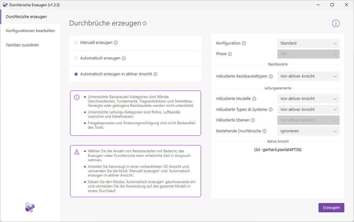
Settings during creation
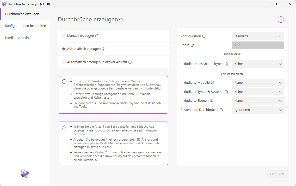
Let's first take a look at the settings in "Automatic Generation" mode.
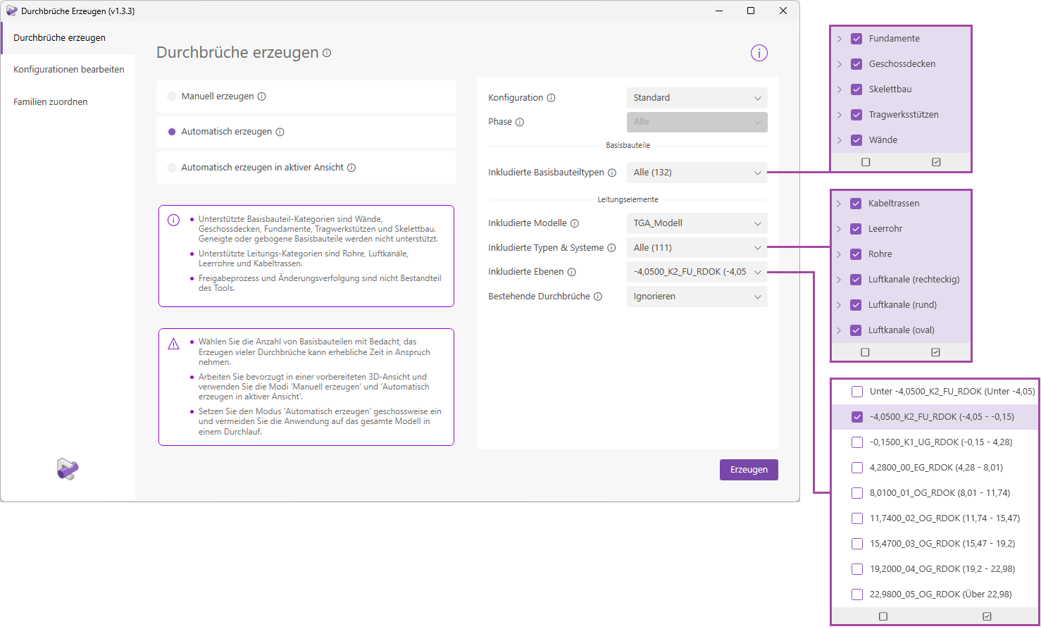
- Configuration:
Select the configuration you created under "Edit Configuration" or use one of the default configurations. The configuration determines the shape and dimensions of the openings depending on the type/system. - Phase:
The selected phase defines which base components are used for the clash detection. All elements created at the time of the selected phase and not canceled are taken into account. If there are no more than 2 phases in the model, the option is grayed out and all phases are used for the collision check. - Included Base Component Types:
Select the base component types for the clash detection. Only types with a valid prefix are displayed: GeDe, TrSt, Wall, Skel, BoPl, FuPl, Fund, FuWa. When making your selection, note that elements with incorrect type names (e.g., Wall_Tiles_015) would also be available here. Check the types carefully before placing them to avoid incorrect placements. - Included Models:
Select all models whose line elements should be available for the collision check. These can be linked models, but the active model is also available for selection. - Included Types and Systems:
All types and systems of the selected models are displayed here; the list therefore depends on the model selection and updates as soon as the model selection changes. Systems from linked models are prefixed here with the corresponding model name. - Included Levels:
By selecting levels here, you choose the area to be used for the clash detection. Only clashes that actually lie within this area will be marked with a break-through. Note that the selection "5,0000_00_EG_RDOK (5.00 - 8.50)" does not include the floor slab with "Level 5,0000_00_EG_RDOK". However, the floor slab with level "8,5000_01_OG_RDOK" is included. - Existing Openings:
The add-in saves all previously resolved collisions, i.e., collisions for which an opening has already been created. The pipe element and the associated base component are saved together.
If, during a new placement process, you select a pipe element and base component whose collision has already been resolved by "Create Openings," you can use this setting to decide how the placement should now proceed.
With the "Delete and Reposition" option, the clearances for already resolved collisions are deleted in the first step, but only if the pipe element and the base component of this collision have been selected for the placement process. The placement process is then executed as usual.
With the "Ignore" option, only a new collision check is performed. This will generally not result in new collisions for already resolved collisions, since breakthroughs already exist there. However, if a line element has moved, this will result in a new collision, and another breakthrough will be created.
Note: Breakthroughs that were not created by "Generate Breakthroughs" are generally ignored.
The same settings are available in the "Generate automatically in active view" placement mode. However, the "From active view" option is preselected so that you can start generating immediately. You do not need to select any layers; the 3D clipping plane defines the boundaries.
In the "Manual Creation" placement mode, you do not need to configure these settings, as you select the elements directly.
Types of Families
The types of family elements used to create cutouts are determined automatically. To do this, "Create Cutouts" examines the line elements to identify their trade, and then places the appropriate cutout types.
- Electrical Line
Elements Elements in the Cable Trays and Conduit categories are assigned to the 'Electrical' trade. Accordingly, a cutout with the family type 'Electrical' is generated for these elements. - HVAC ductwork
elements Elements belonging to the HVAC trades are identified based on their system type. The fifth character serves as an identifier for the trade.
Example: The system with the system type '200_H_VL' corresponds to the heating trade.
The opening family types are assigned as follows:- System with identifier H = cutout family type 'Heating'
- System with identifier K = Penetration family type 'Cooling' or 'Refrigeration'
- System with indicator L = Breakthrough family type 'Ventilation'
- System with code S = Breakthrough family type 'Plumbing'
- System with code B = Breakthrough family type 'Fire protection'
Types of families when merging openings:
If openings are combined with different family types, a suitable family type is selected, such as 'Heating, Ventilation, Plumbing'. If there is no suitable family type for the given combination of trades, the family type 'TGA_general' is assigned.
Note: In the standard configurations, there are special settings for electrical openings. Openings for empty conduits are not merged. Openings for cable trays are only merged with other openings generated by cable trays. You can, of course, adjust these settings to suit your needs.
Collision detection
The clash detection feature is a key component of this Revit add-in. But which elements are actually allowed, and how does it work in detail? This section explains the underlying logic.
Base components: Only elements that are exactly horizontal or vertical are taken into account. Sloped floor slabs and foundations are ignored, as are sloped, tapered, or curved walls. Furthermore, floor slabs to which points have been added through shape editing are ignored.- Pipe elements:
A collision is only permitted if the intersection angle between the base component and the pipe element is not less than 30° (for vertical base components/surfaces, e.g., walls), or not less than 45° (for horizontal base components/surfaces, e.g., floor slabs).
Categories currently considered include pipes, air ducts, conduit, and cable trays. Ductwork elements not currently considered include, for example, fittings (cable trays, pipes, air ducts) and accessories (e.g., fire dampers).
Note - Borrowed elements:
Elements that are currently being used by other users are ignored during the collision check.
Note - Processing areas:
In "Automatically Generate" placement mode, elements whose editing area has not been loaded are also collected. These are therefore also included in the collision check. When checking for cutouts, the corresponding editing areas are loaded to make the components visible in the control views.
Characteristics of the breakthrough
When creating cutouts, a variety of settings are applied to them; these are described in detail here.
Machining area: Always corresponds to the machining area of the base part.
Phase: Always corresponds to the phase of the base component.
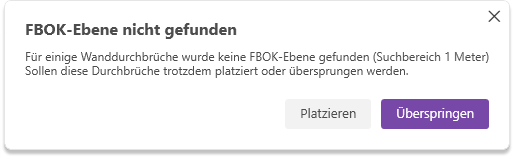
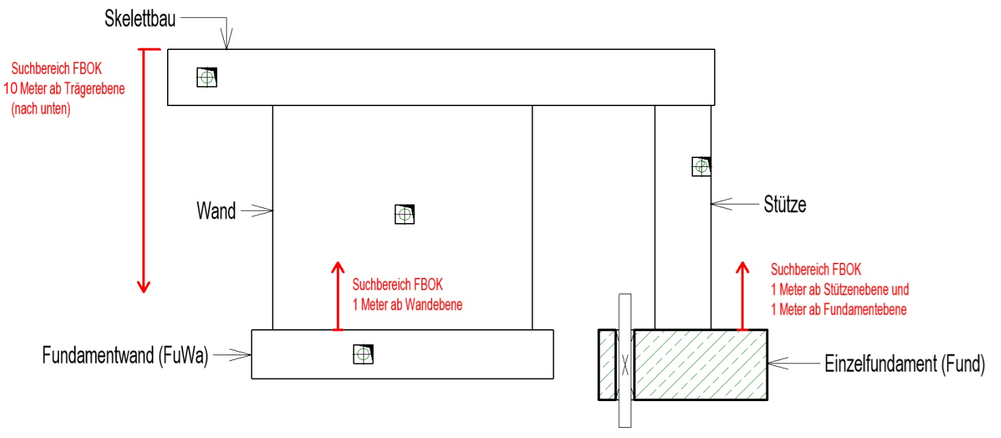
Level (Wall): Without exception, an FBOK level must always be assigned to openings. For wall openings, the corresponding level is determined as follows: Starting from the base plane of the wall, a search is performed within a 1.00 m range upward for a plane that contains the term "FBOK" in its name. Floor planes take priority in this process. If no corresponding FBOK plane is found, a warning is displayed.
- Component list level (TrSt, Skel, Fund, FuWa):
The same rule applies here: Openings must always, without exception, be assigned an FBOK level. This is determined as follows, depending on the category.
TrSt, Fund, FuWa: Starting from the base level of the base component, a search is conducted within a range of 1.00 m upward for a level whose name contains "FBOK." Floor levels take priority in this process.
Skel: Starting from the base level of the base component, a search is conducted within a range of 10.00 m downward for a level whose name contains "FBOK." Floor levels take priority here as well.

This parameter is set to 0.00 for wall openings.
Parameter is calculated and set.
- "View depth at bottom" is set to 2.00 m (only for Allg_BD and Allg_DB_Fläche_Oben families).
- "Top Symbol View Area" is set to 0.10 m (only for Allg_DB_Fläche_Oben families).
- "Floor Structure Height" is set to 0.35 m (only for Allg_BD families).
The parameter is populated with the username and the date the breakpoint was set.
Width, height, length, depth, and diameter are calculated and applied based on the configuration.
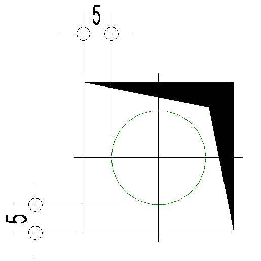
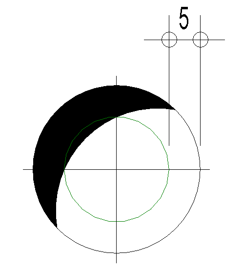
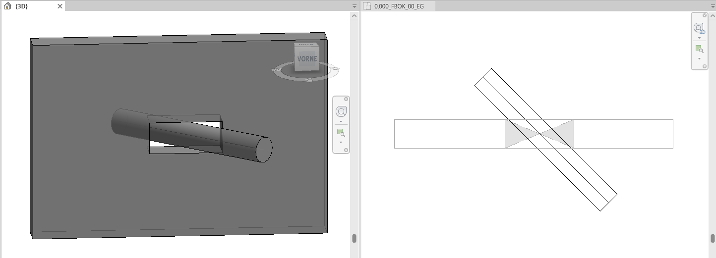
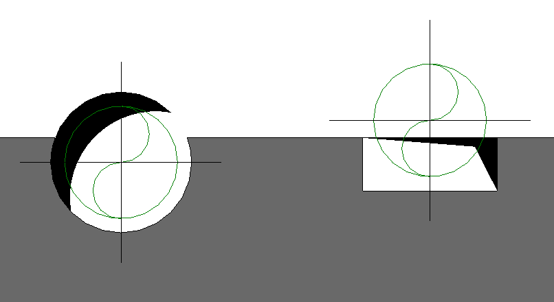
When placing round cutouts, there are certain special considerations to keep in mind. If the intersecting line element is not perpendicular to the base component, a rectangular cutout is automatically created. Round cutouts are therefore created only when the intersection angle is 90°.
See the following example with a 45° intersection angle:
Errors and warnings
While generating cutout families, Revit continuously displays errors and warnings. To prevent these from constantly opening error dialog boxes that interrupt the placement process, the "Generate Cutouts" feature automatically resolves common errors. In this section, we’d like to explain how this works in detail.
Errors:
- No instance(s) of TGA_Allgemein intersect with any other object.
- Instance(s) of TGA_General cannot be cut out of the base component.
- Instance of TGA_General cannot be cut out of a wall.
- The type "Allg_WD_rectangular : TGA_General" cannot be created.
Solution: The breakthrough instance is deleted.
Error:
- Elements cannot remain connected.
- A connected element cannot be cut.
- Changes to groups are only allowed in group editing mode. Use the Edit Group command to apply the change to all instances of the group type. You can use the "Ungroup" option to proceed with this change by ungrouping the modified group instances.
Solution: All breakthrough instances just created in this base component are deleted.
Error:
- One or more dimension references are invalid or have become invalid.
Solution: The relevant dimensions (dimension lines, elevation marks, etc.) are deleted.
Warnings:
- Instances of TGA_General cannot be cut out of the base component.
- The highlighted inserted elements overlap with other inserted elements or do not touch the associated base components at all.
- The inserted element causes a conflict with the connected wall.
Solution: Warnings are suppressed when the model is generated, but continue to be displayed in Revit afterward.
The following examples illustrate both the placement and the verification processes.
Create & Check
Open any view in which you want to create cutouts. This can be either a 2D or a 3D view.
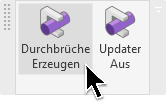
Click the "Create Openings" button to launch the corresponding Revit add-in.
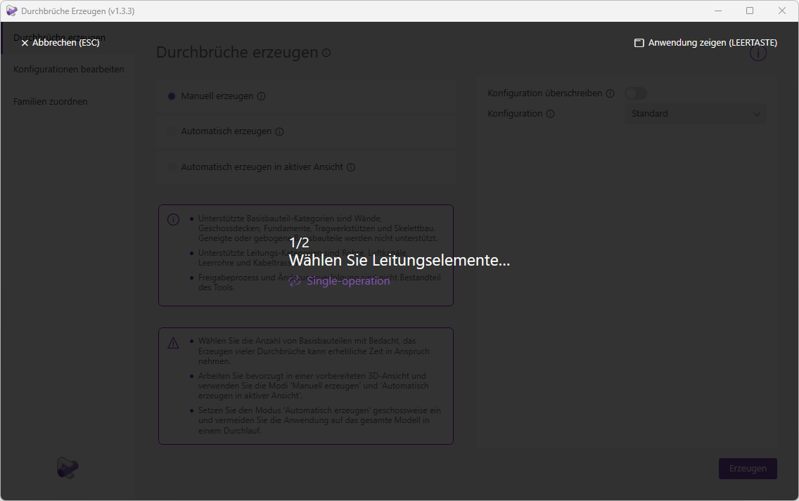
The user interface opens. We are now in "Manual Creation" placement mode.
Tip:
- The "Override Configuration" button allows you to easily set options for the current placement. Instead of switching to "Edit Configuration" mode, changing settings, saving them, and returning to "Generate Breaks" mode, you can override the settings directly and temporarily here.

In this example, we will proceed without overwriting the configuration. We will use the "Standard" configuration.
Clicking the "Create" button takes you to selection mode. The user interface will now guide you through the selection process. Note that we are using the "Standard" configuration for placement.
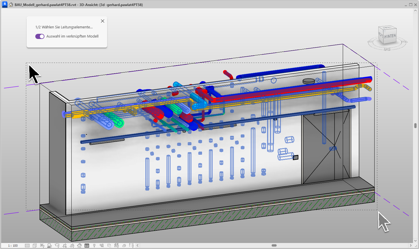
We enable the "Selection in linked model" checkbox, since our line elements are located in a linked model. Next, we drag a selection frame over all line elements in the view. However, you also have the option to select or deselect individual elements with a mouse click.
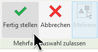
We confirm the selection by clicking the "Finish" button on the Revit ribbon (at the top).
Now select the wall by clicking on it. Alternatively, you can select as many basic components as you like here.
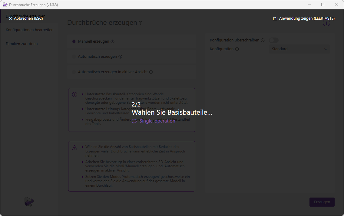
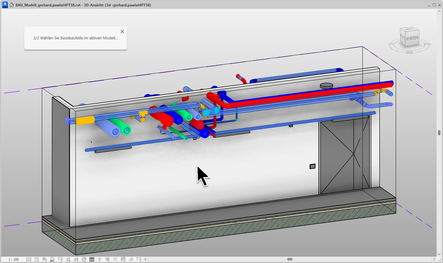
We confirm your selection.
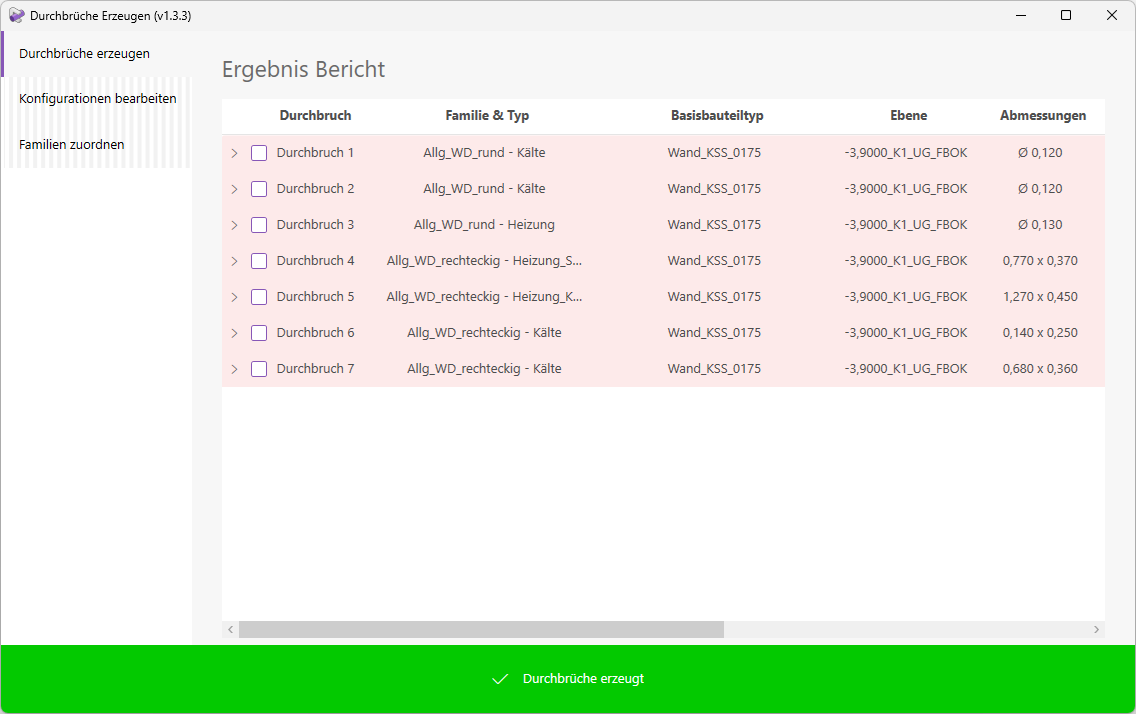
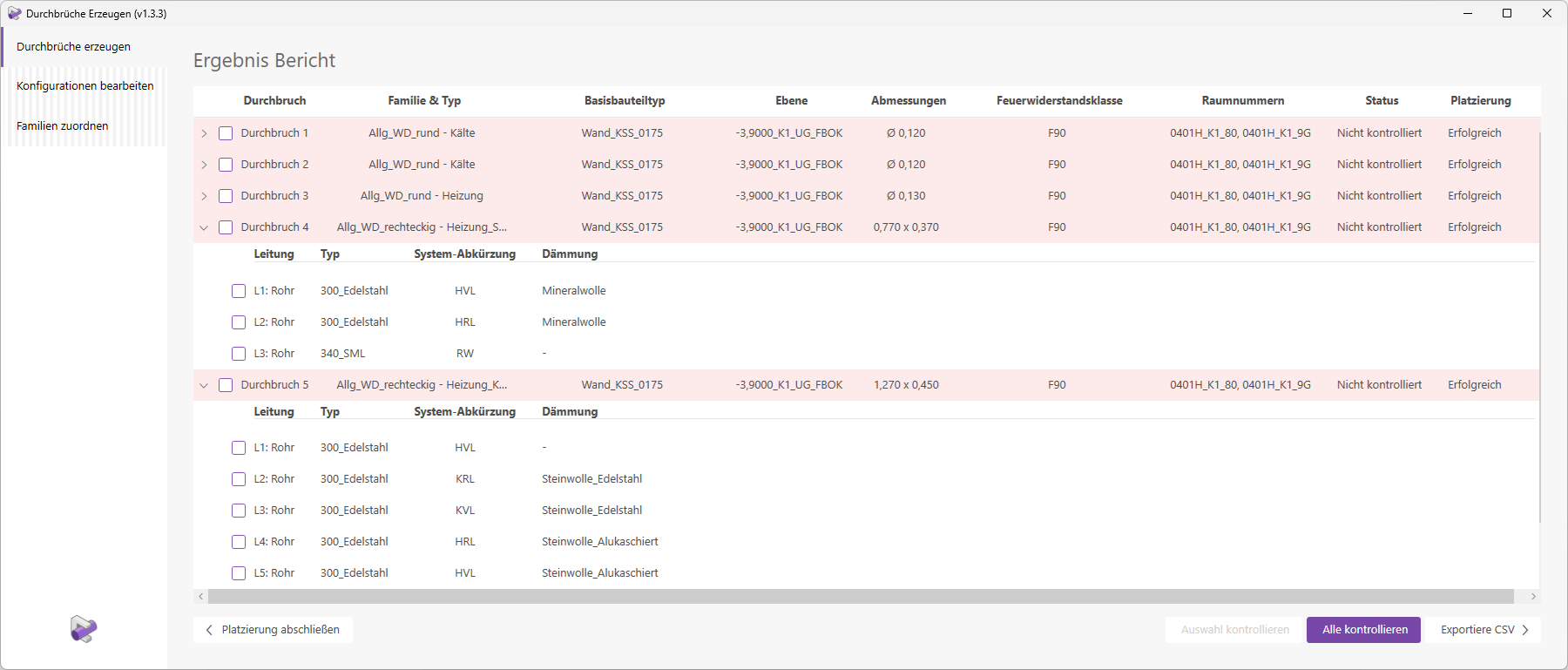
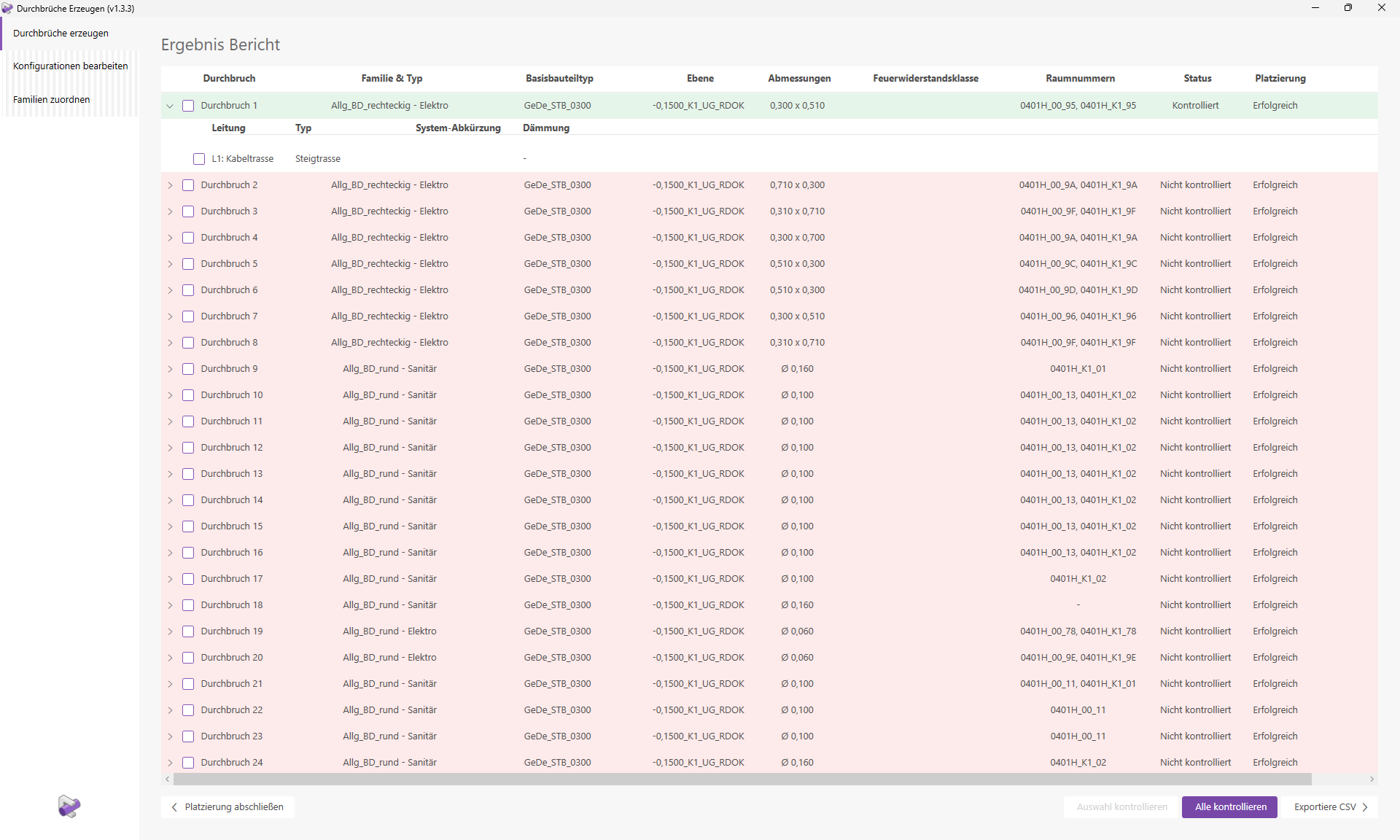
We can see that all openings have been placed successfully. Various details, such as the layer, room numbers, and dimensions of the openings, are displayed. Regarding the families and types, it is noticeable that both round and rectangular openings have been placed. This is because some round openings were merged into a single rectangular opening. The corresponding settings are defined in the configuration we used for placement.
It is also noticeable that there are openings that have been assigned to multiple trades.
Opening 4 was created with the type 'Heating_Plumbing'. Opening 5, on the other hand, was assigned the type 'Heating_Cooling'. The type assignment is performed automatically based on the trades of the pipes creating the openings. Each opening row can be expanded to view information about the corresponding pipe elements. Let’s take a closer look at openings 4 and 5.
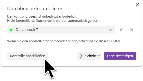
Clicking the "Check All" button starts the necessary verification process. This generates optimized verification views that allow you to easily check the placement visually.
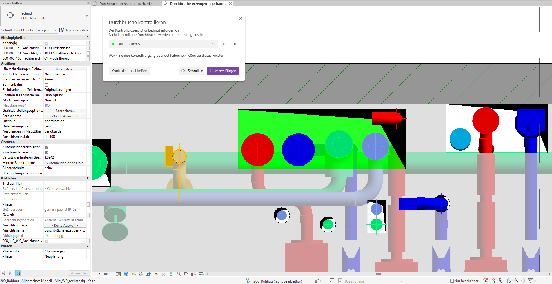
The navigation window and the first verification view will open.
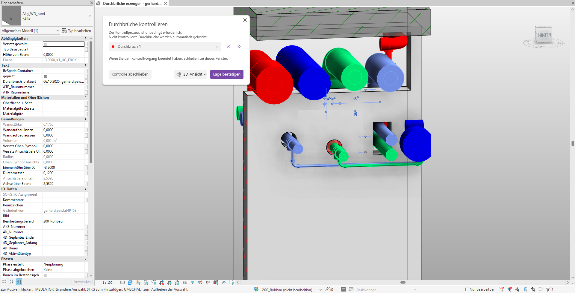
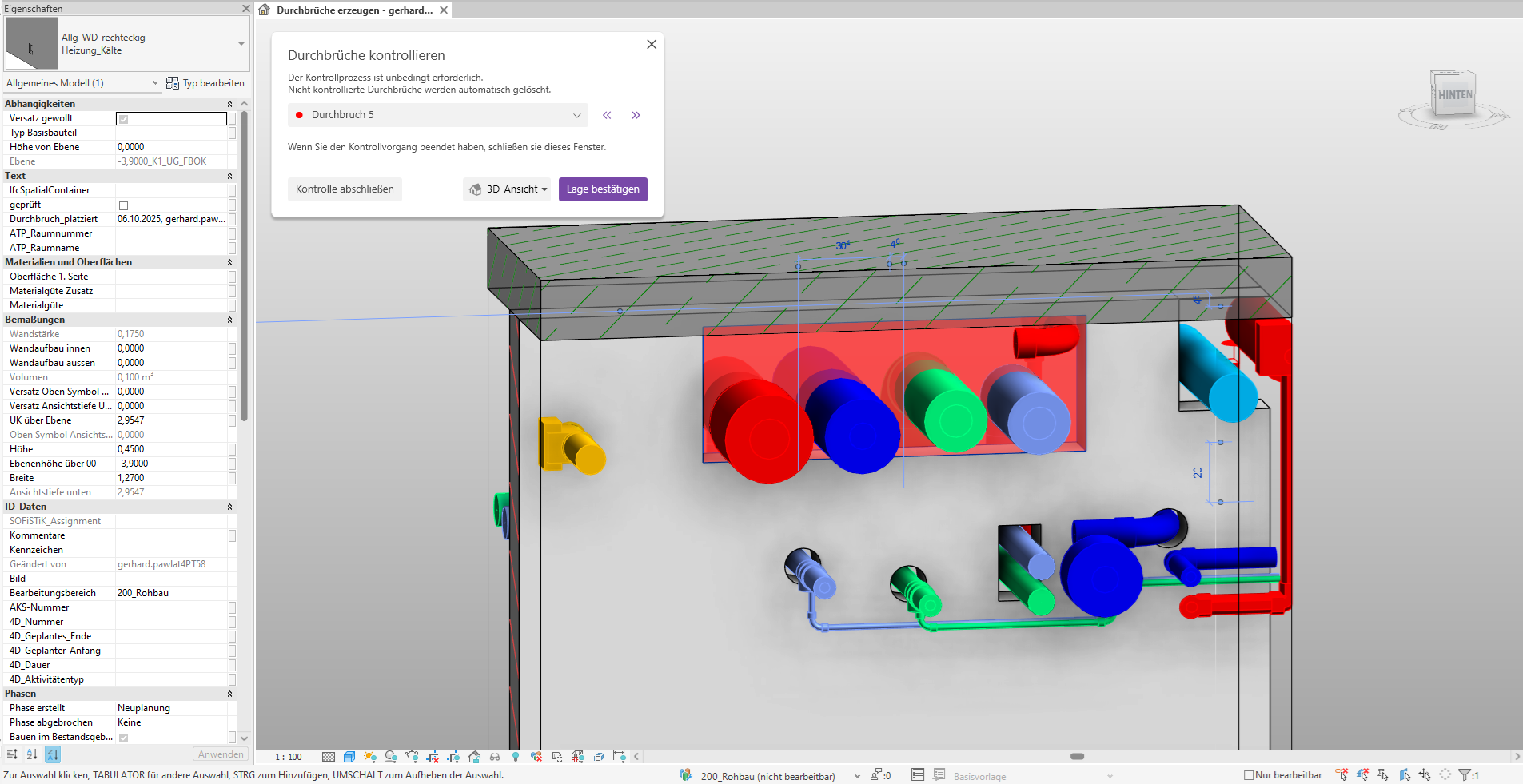
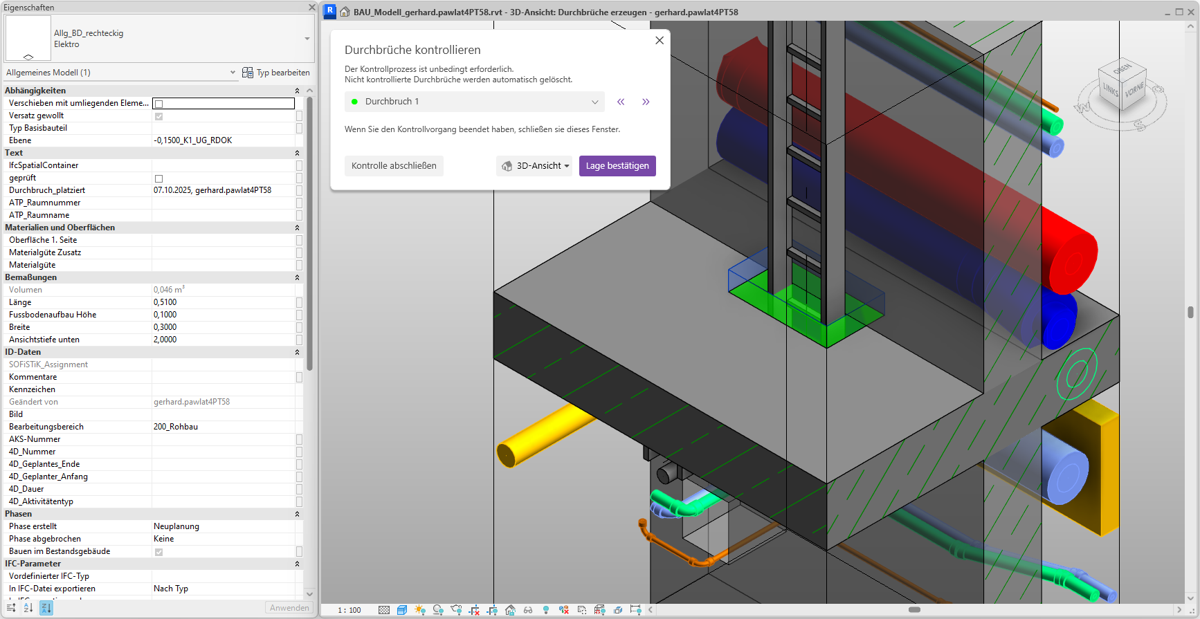
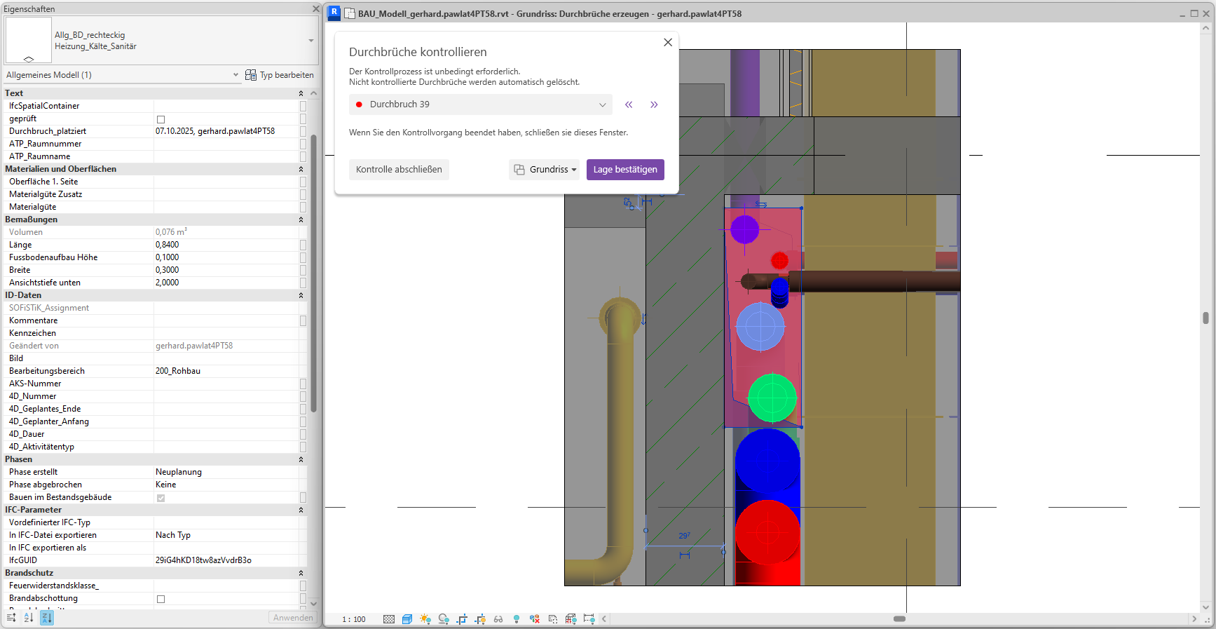
Cutout 1 is centered in the view and marked in red. The fill color corresponds to the cutout’s status. Furthermore, the cutout is already selected, so you can see its parameters directly in the Properties window. Now check the position of the opening and make any necessary adjustments.
Tip: The control views contain various view filters. Adjust these as needed.
Since the opening has been placed correctly, we confirm with the 'Confirm Position' button; the opening is now marked in green.
A corresponding 2D preview window opens.
Since the cutout was positioned correctly, we confirm its location, and the cutout indicator turns green.
Finally, we'll wrap up the placement.
The placement has been successfully completed.
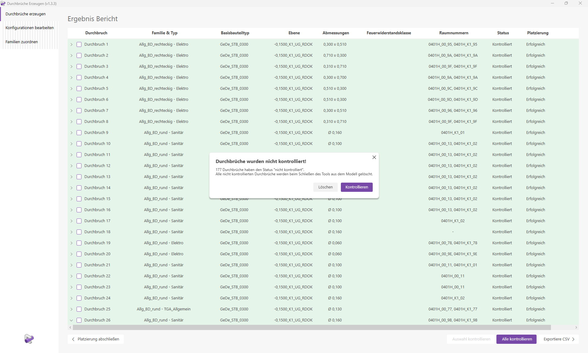
Note:
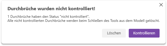
Openings whose control status has not been set to 'Controlled' will be deleted from the model. You will be notified of this via a warning message. The deletion of uncontrolled openings must be explicitly confirmed.
Click the "Create Openings" button to launch the corresponding Revit add-in.
The user interface opens. We select "Auto-Place" mode and configure the following settings.
Note: For placement, we select only one layer. Creating cutouts for all base components and all cables in a complete model can result in several thousand cutouts and long computation times for large projects.
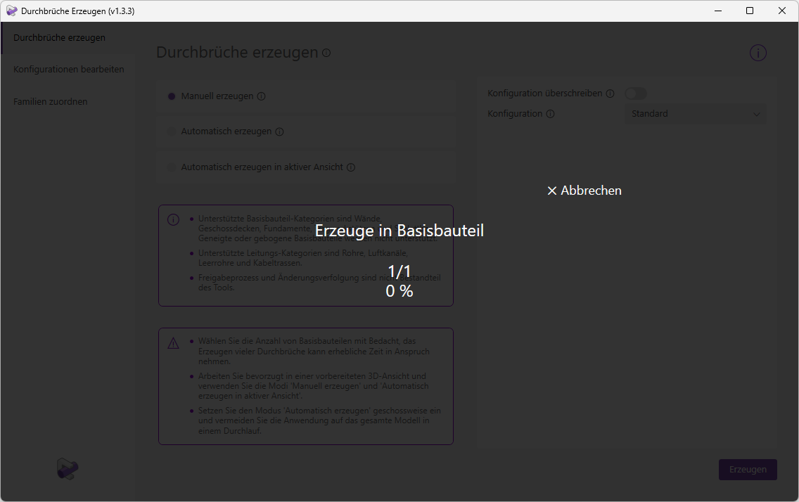
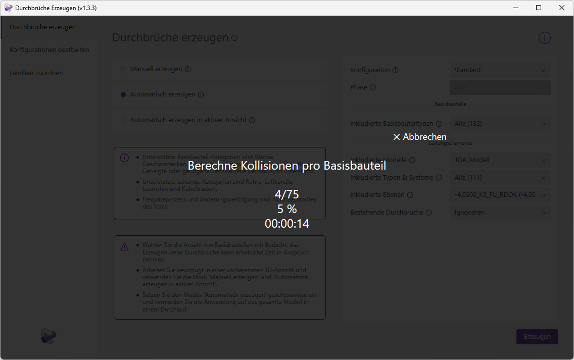
"Generate Cutouts" will now begin the calculation and placement process. Various details regarding the progress will be displayed. The progress percentage and remaining time refer to the current operation, e.g., "Calculate Collisions per Base Component." The display showing which element is currently being processed, e.g., 4/75, always refers to the base components.
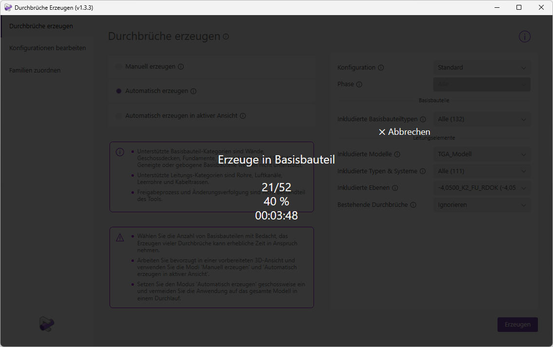
Note: When creating openings in a floor slab, the progress bar often does not update for an extended period and appears to be frozen. This is because a floor slab can contain hundreds of openings. The status will update as soon as all openings have been created in the base element.
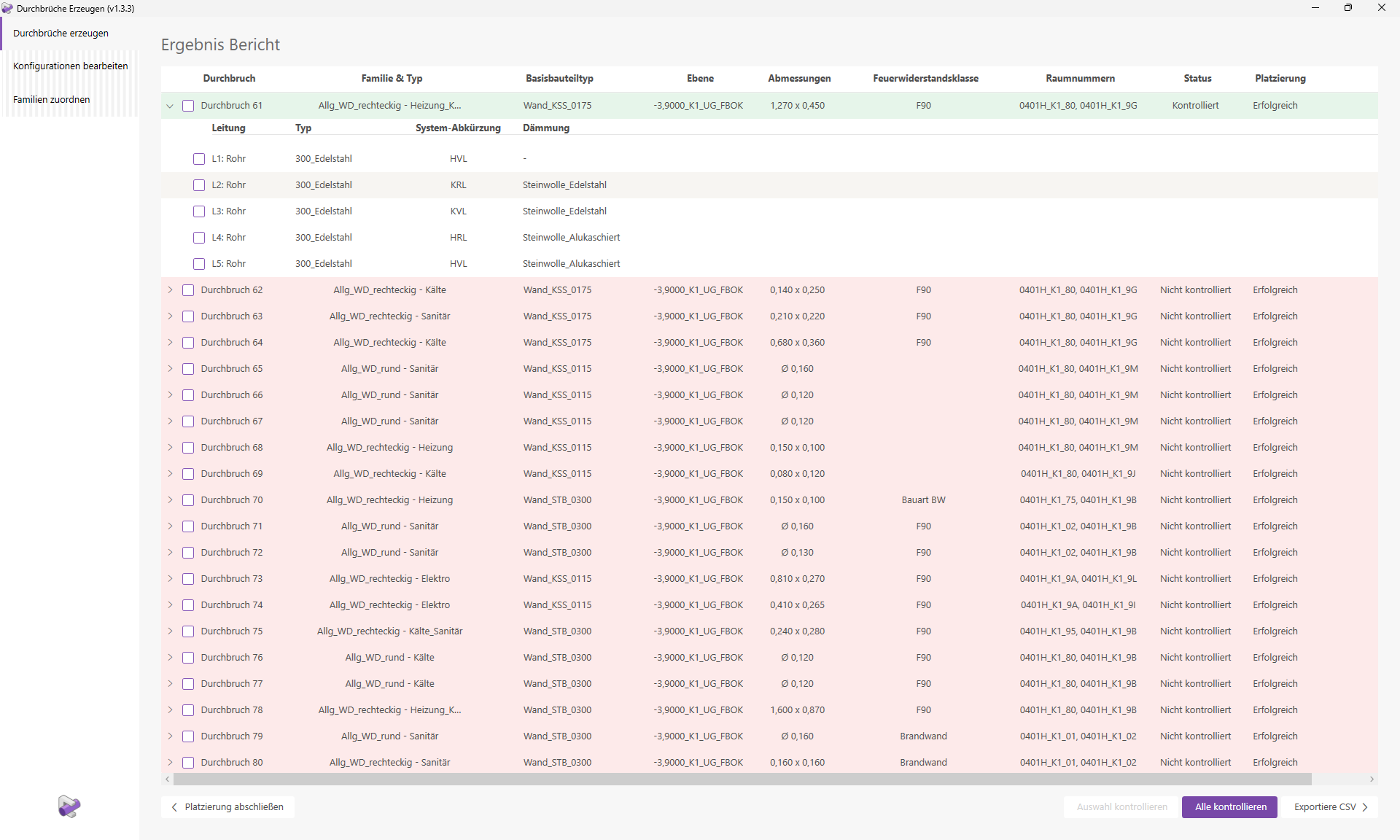
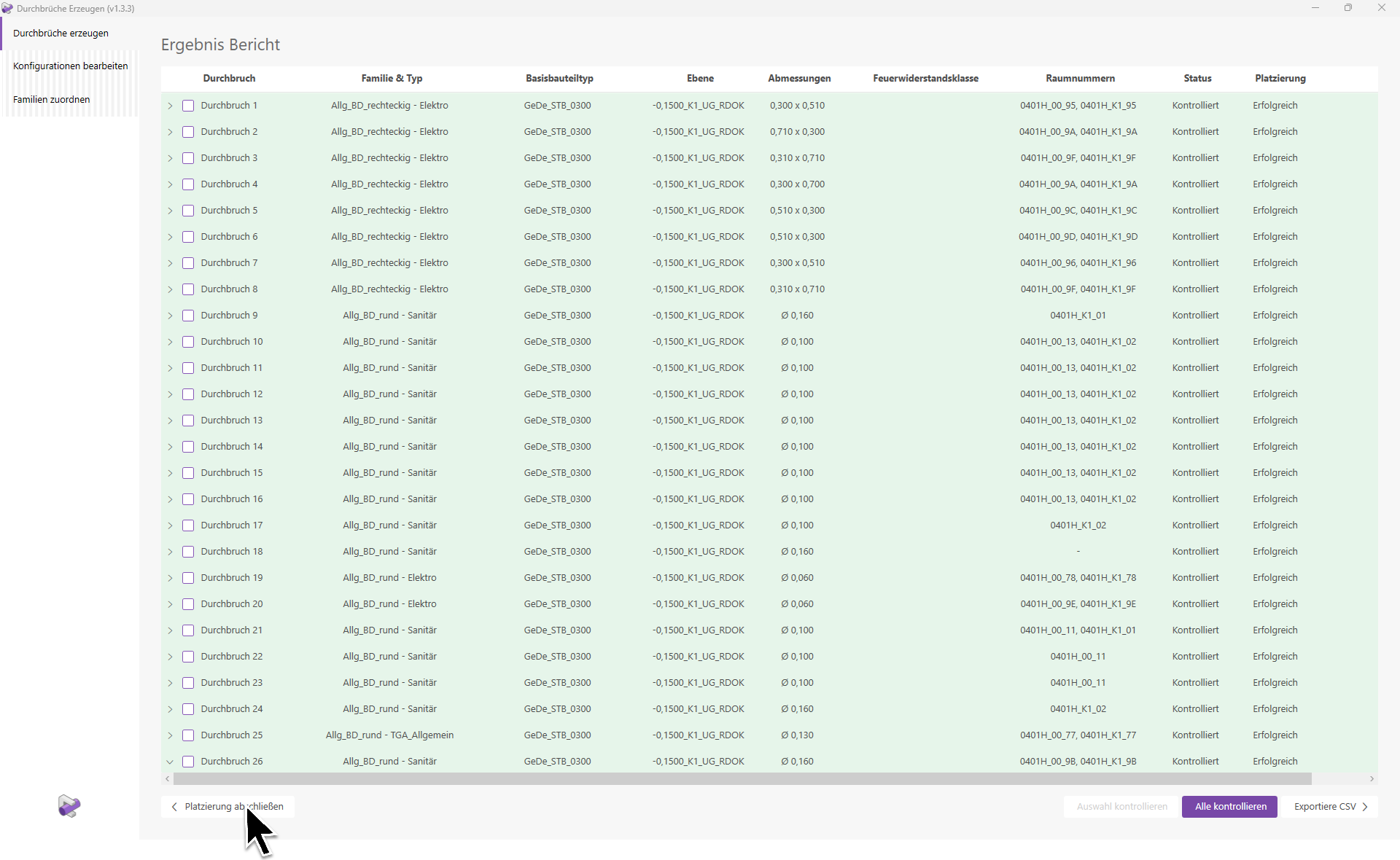
The results report will then open.
Let’s also take a look at the last few lines of the report.
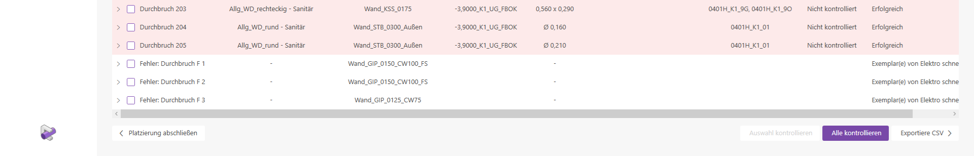
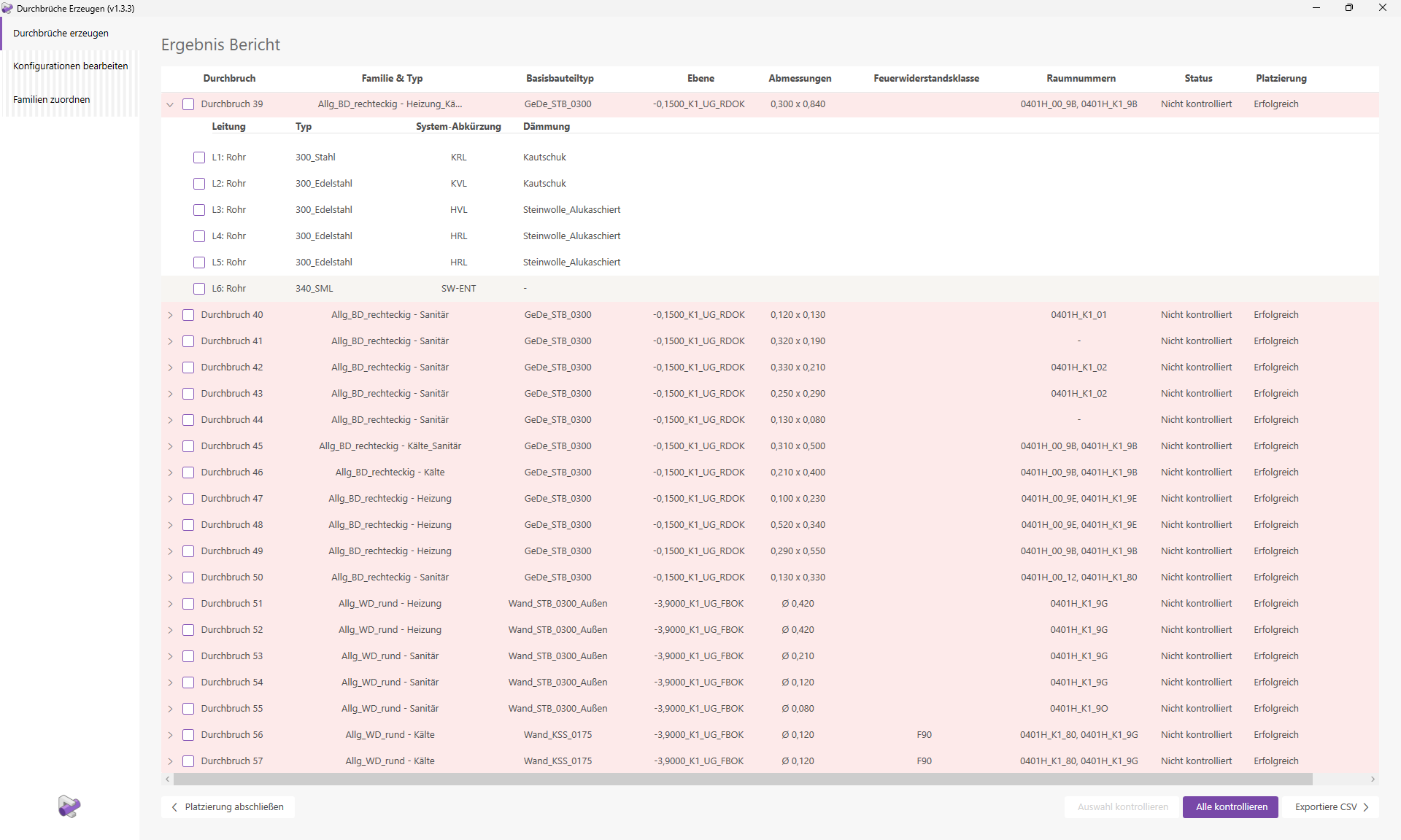
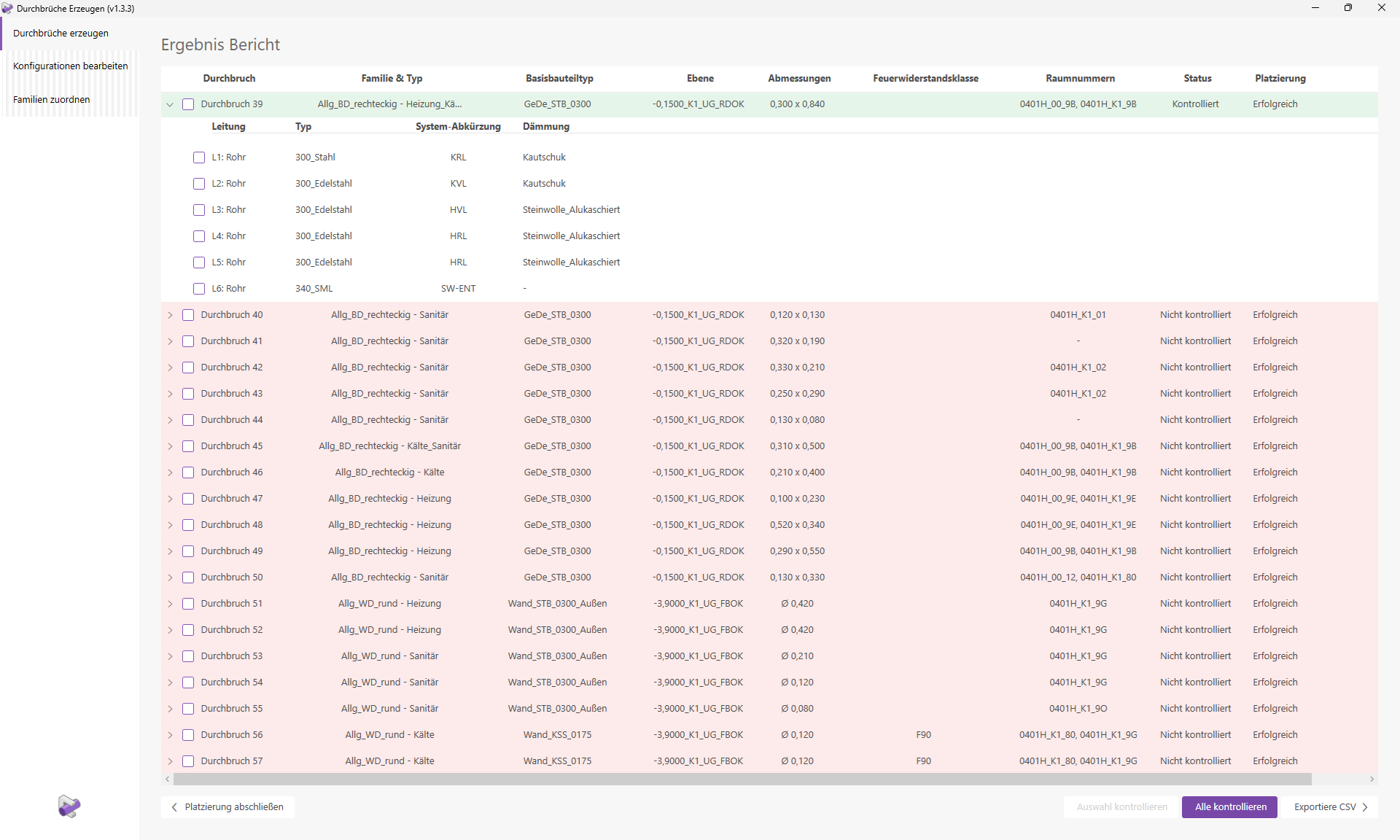
We can see that 205 breakthroughs were marked as "Successful." However, three breakthroughs are shown as having errors. We will take a closer look at these at the end of this guide.
Various details, such as the layer, room numbers, and dimensions of the openings, are displayed. It is noticeable that both round and rectangular openings have been placed in the families and types. This is partly because different opening shapes are assigned to different conduit categories. On the other hand, some round openings have been combined into a single rectangular opening. The corresponding settings are defined in the configuration we used for the placement.
Furthermore, it is noticeable that there are openings that have been assigned to multiple trades. Each opening row can be expanded to view information about the corresponding conduit elements. Let’s take a closer look at openings 37 and 38.
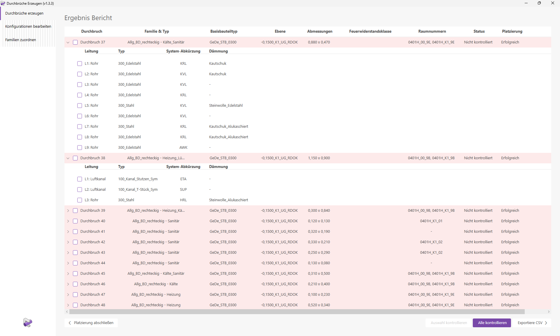
Opening 37 was created with the type "Refrigeration_Plumbing." Opening 38, on the other hand, was assigned the type "Heating_Ventilation." The type assignment was performed automatically based on the trades of the pipes creating the openings. In these cases, openings from different trades were combined into a single, larger opening. For more information on the logic behind type assignment, see the "Family Types" section.
Clicking the "Check All" button starts the necessary verification process. This generates optimized verification views that allow you to easily check the placement visually.
The navigation window and the first verification view will open.
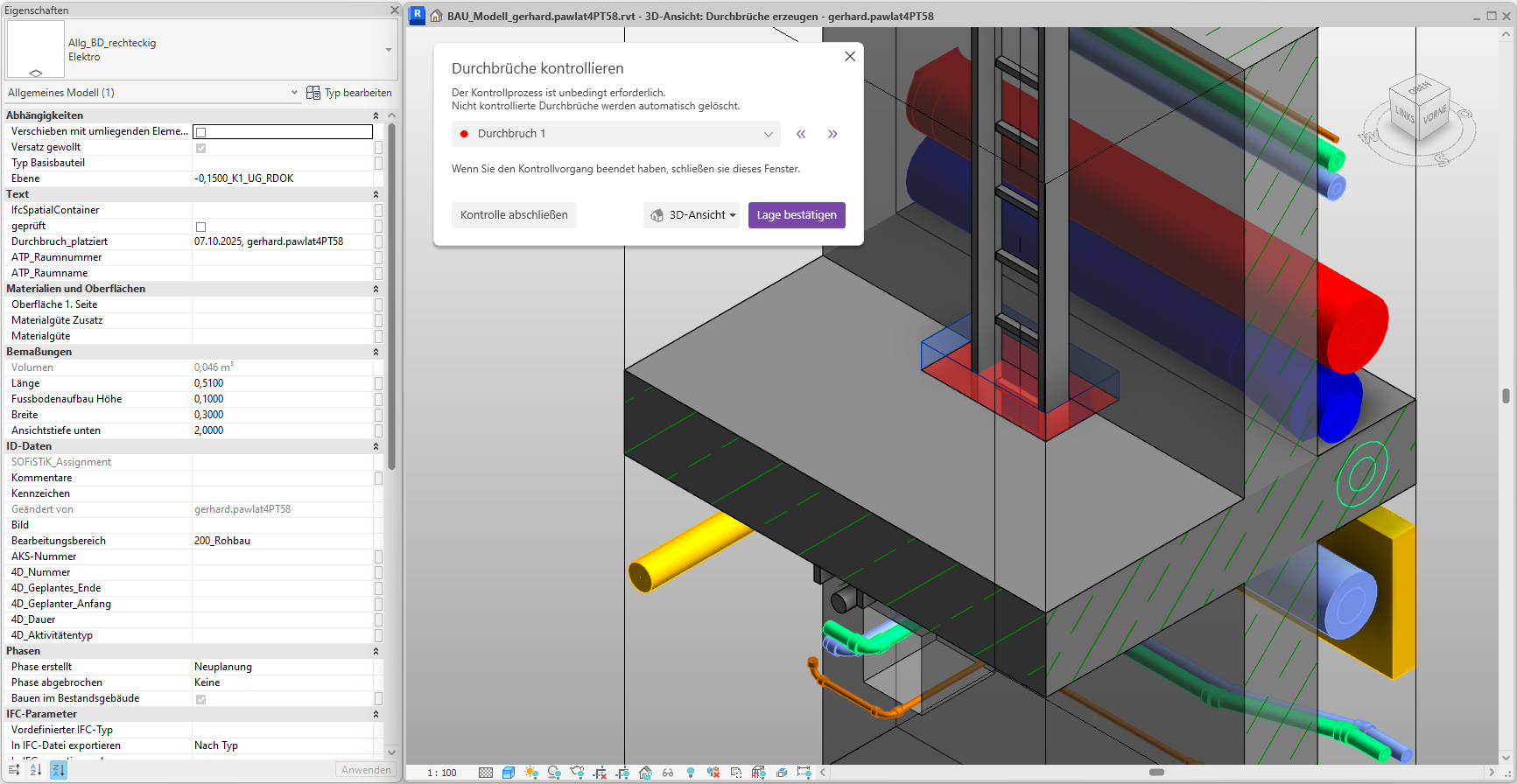
Cutout 1 is centered in the view and marked in red. The fill color corresponds to the cutout’s status. The cutout is already selected, so you can see its parameters directly in the Properties window. Now check the position of the cutout and make any necessary adjustments.
Tip: The verification views contain various view filters. Adjust these as needed.
Since the opening has been placed correctly, click the "Confirm Position" button.
The opening is now marked in green and its status changes to "Verified."
Tip: Keep the results report open on a second screen during the inspection process. Changes to the breakthrough parameters or the inspection status are also displayed in the results report. In addition, the active breakthrough is expanded in the report.
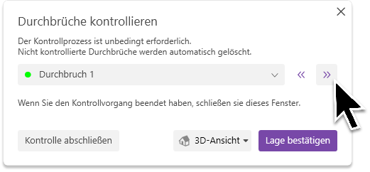
Now use the navigation arrows or the drop-down list to select the next breakthrough for review.
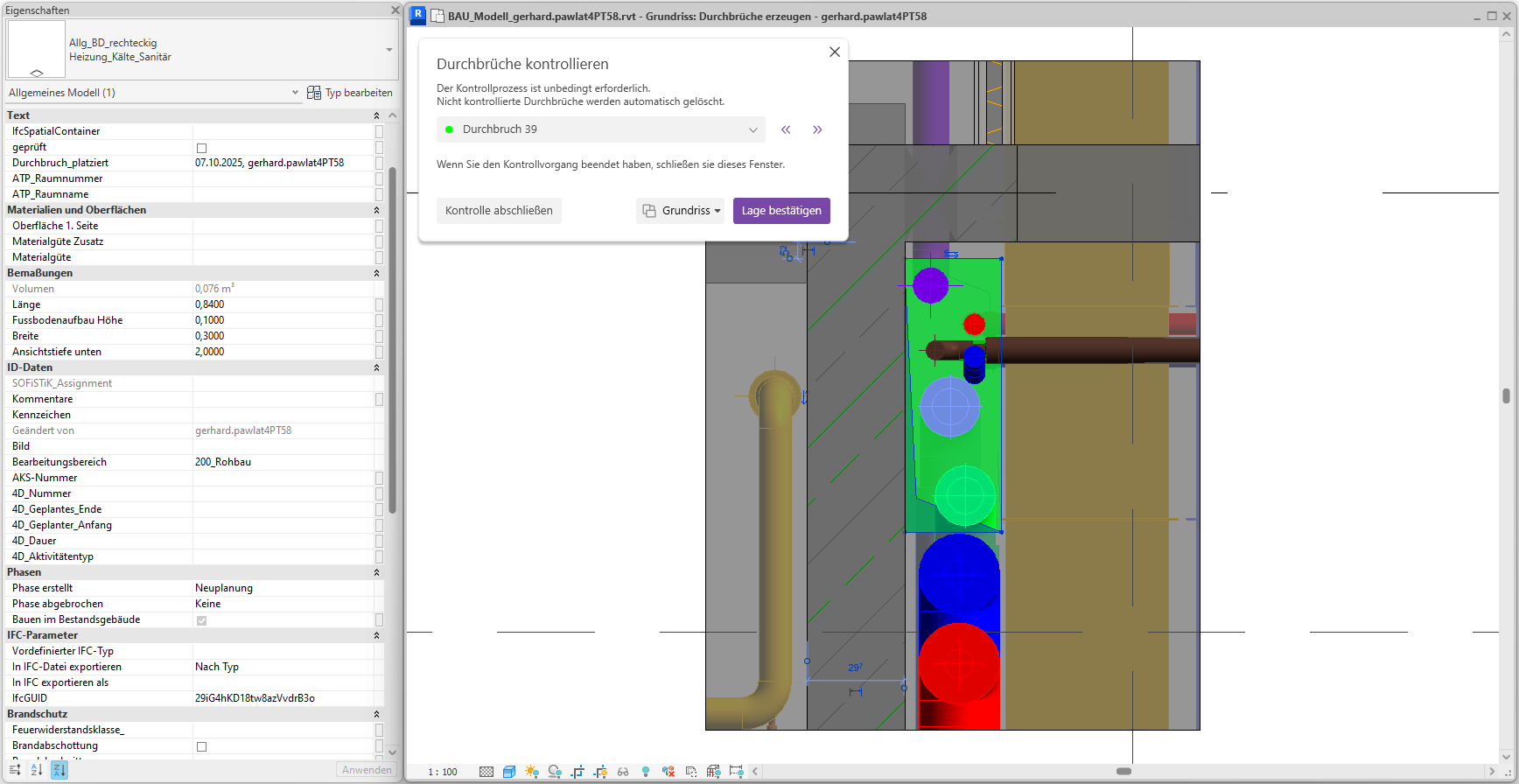
The control view for Breakthrough 39 opens.
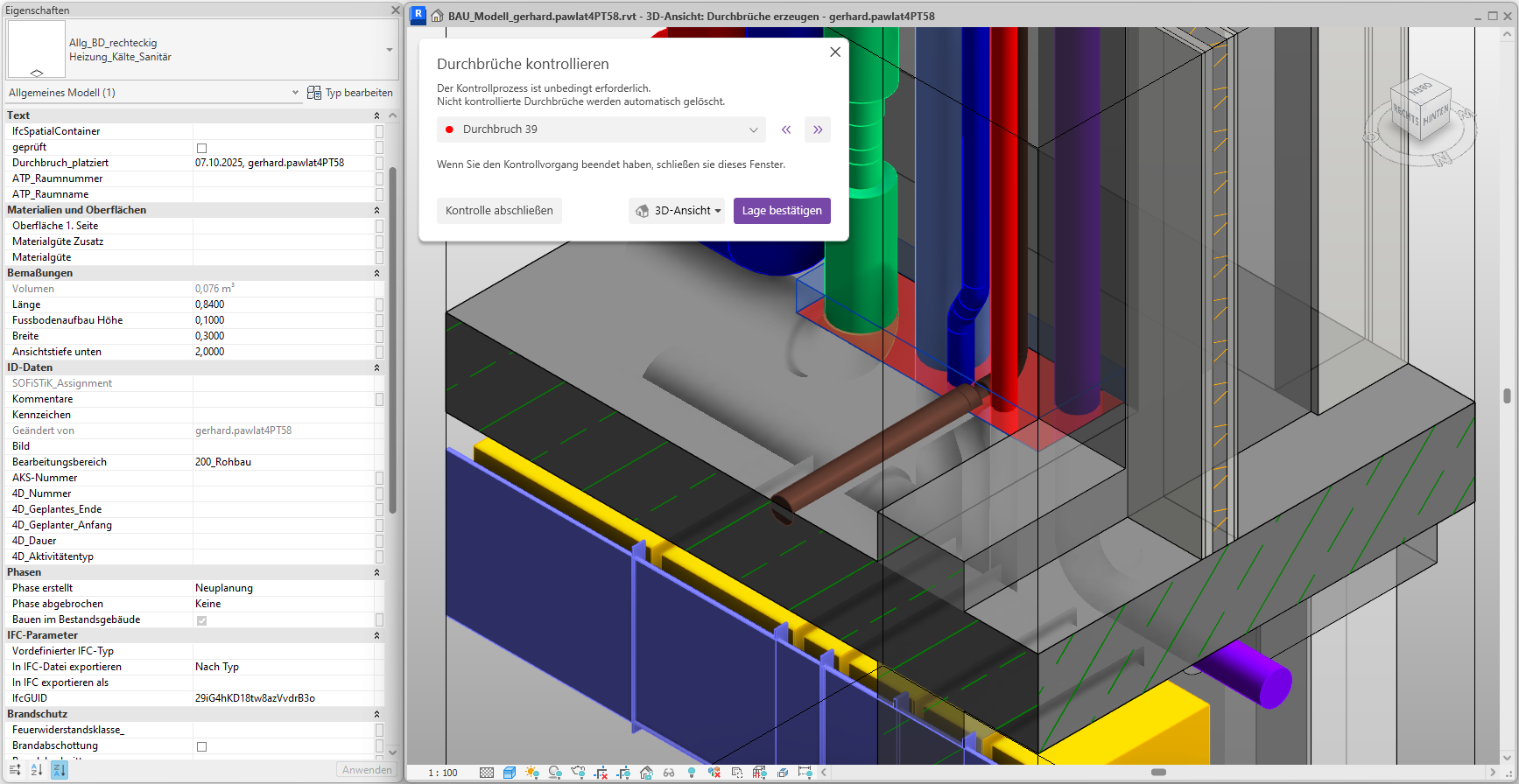
A corresponding 2D preview window opens.
Since the cutout was positioned correctly, we confirm its location. The cutout turns green.
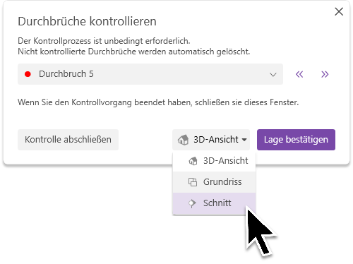
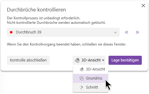
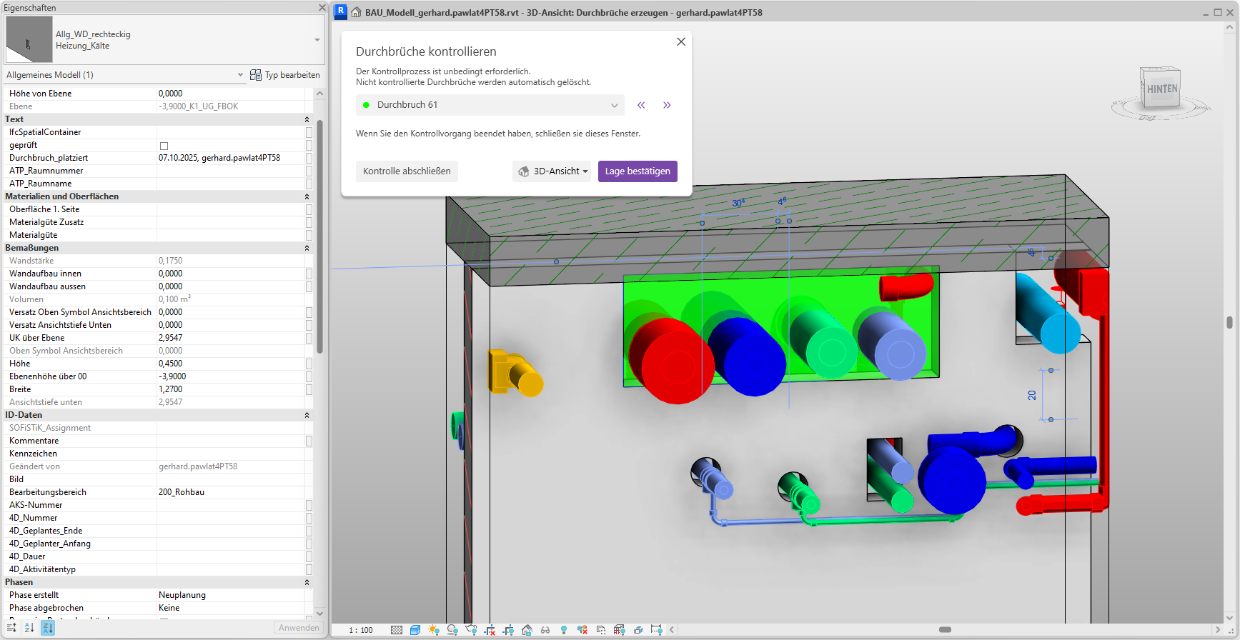
We will now move on to wall opening 61. Since we are currently in 2D mode, a cross-sectional view will be generated.
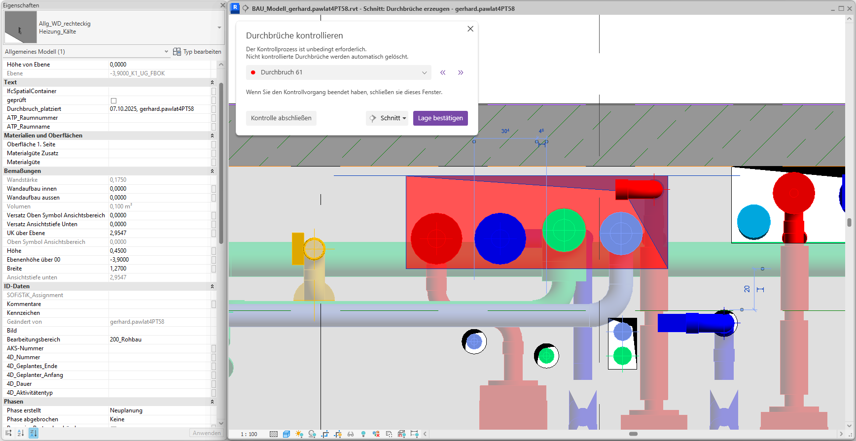
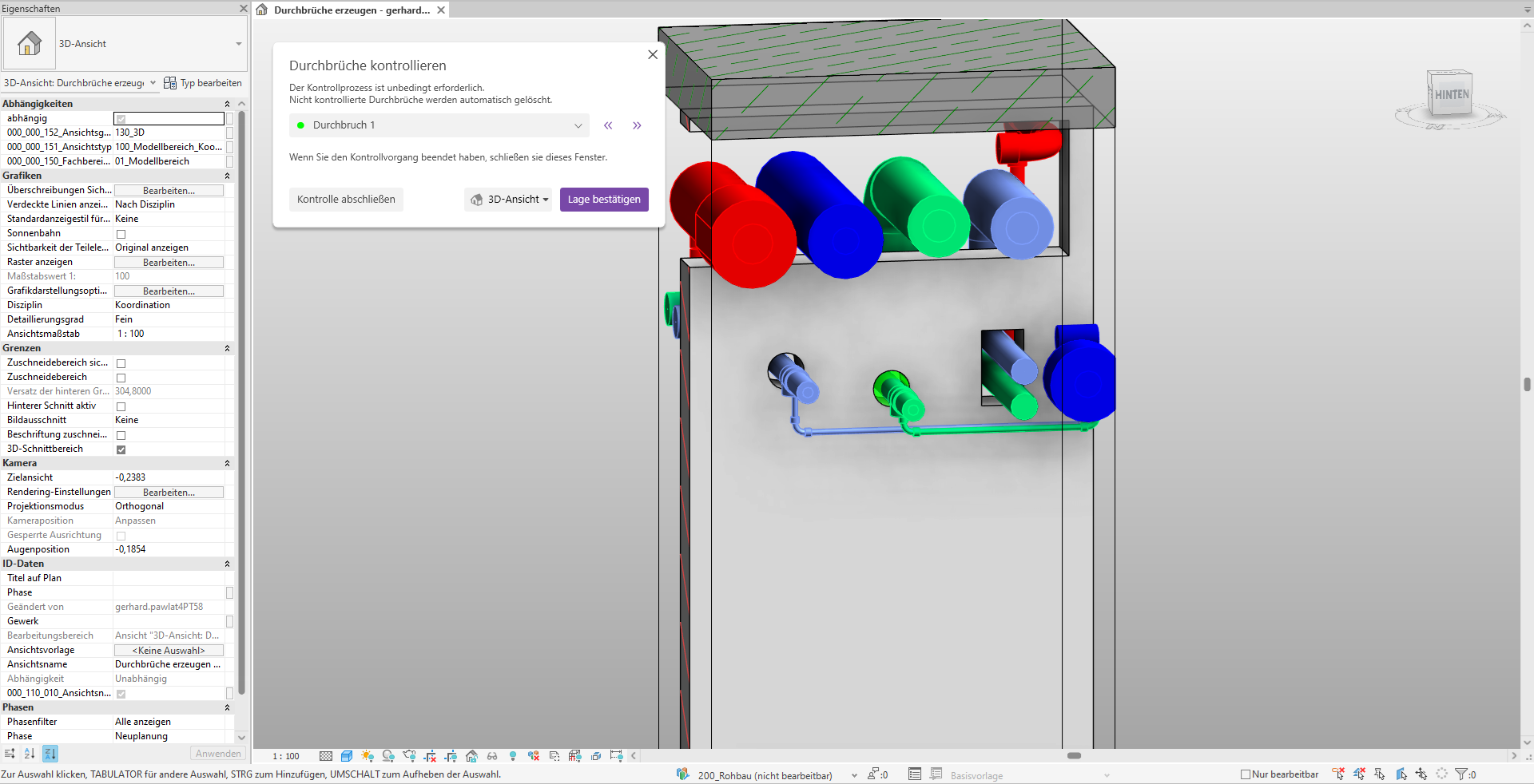
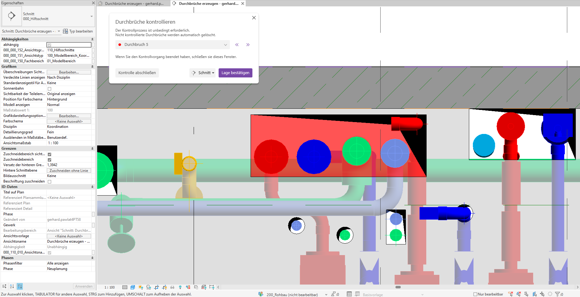
This is another merged cutout. It appears to be positioned correctly. We’ll switch back to 3D mode to check the cutout there as well.
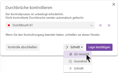
A corresponding 3D view is generated.
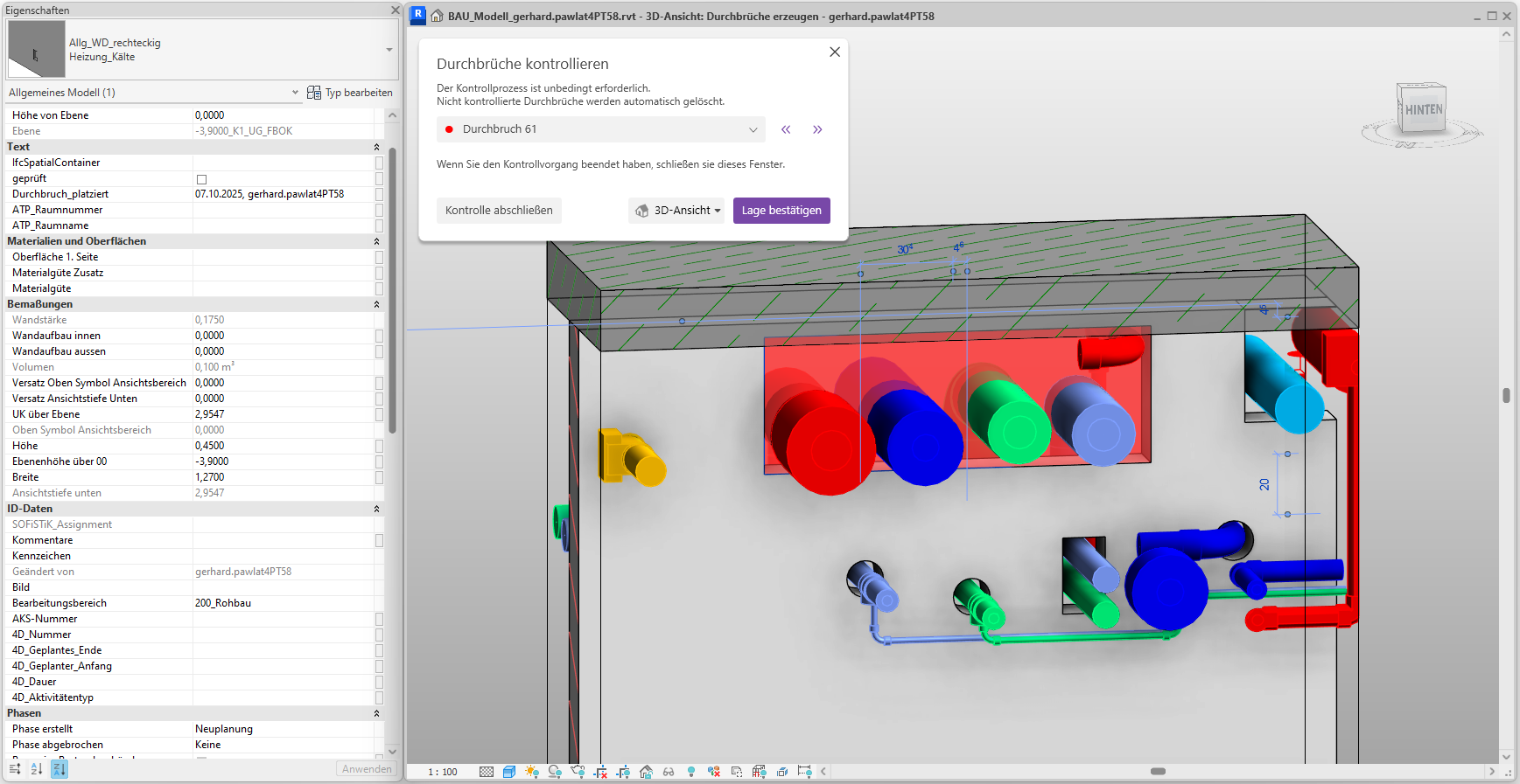
The breakthrough was correctly positioned, and we confirm its location. The breakthrough turns green.
We'll go through all the changes we want to keep in the model and then click the "Finish Review" button.
Finally, we complete the placement by clicking the corresponding button (bottom left).
The placement will be successfully completed provided that all openings have been checked.
Note:
Openings whose check status has not been set to 'Checked' will be deleted from the model. You will be notified of this via a warning message. The deletion of unchecked openings must be explicitly confirmed.
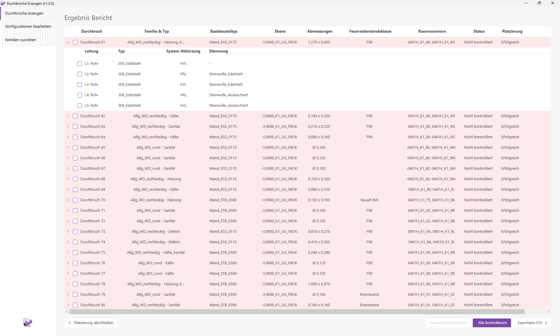
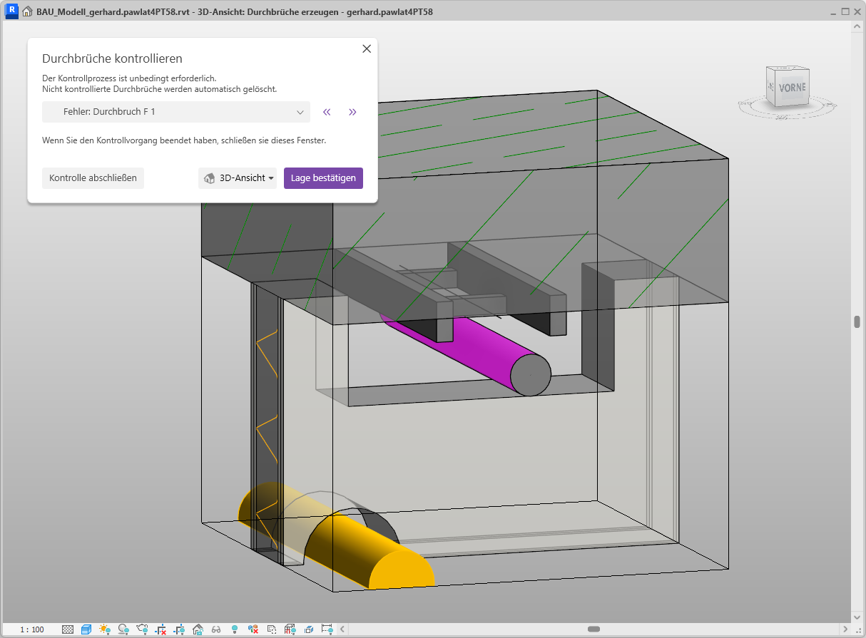
Let's now return to the three faulty breakthroughs.
The "Placement" column displays the corresponding error messages and warnings for incorrect cutouts. In this case, all three cutouts report the same error:
- "No other object intersects with the 'Elektro' object(s)."
To be able to analyze failed placements as well, we can also generate these review views for them. The line elements for which a cutout should have been created are displayed in pink.
Open any 3D view in which you want to create cutouts. 2D views are not allowed in this mode.
Click the "Create Openings" button to launch the corresponding Revit add-in.
The user interface opens, and we select the "Automatically place in active view" mode.
Since we have already customized our view to our liking, we click the button 'Create' without making any further changes.
Note: From now on, this example will correspond exactly to the example 'Create Manually'.
"Create Cutouts" will now begin the calculation and placement process. Information about the progress will be displayed as the process runs. The results report will then open.
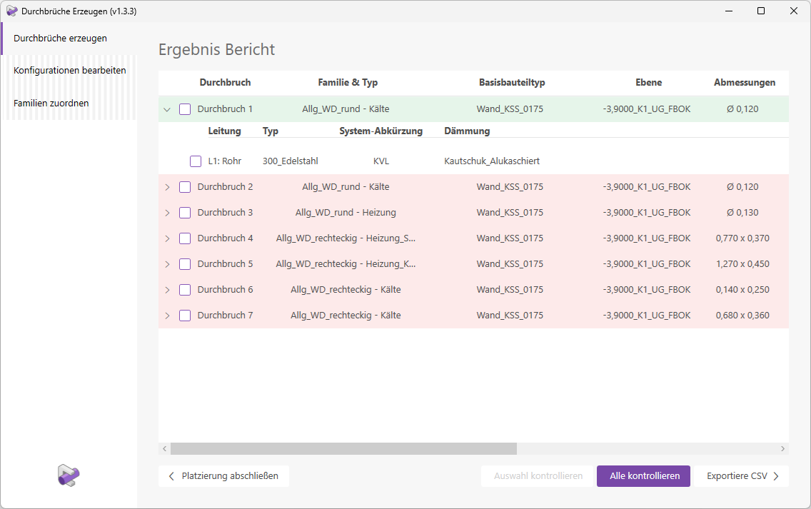
We can see that all openings have been placed successfully. Various details, such as the layer, room numbers, and dimensions of the openings, are displayed. Regarding the families and types, it is noticeable that both round and rectangular openings have been placed. This is because some round openings were merged into a single rectangular opening. The corresponding settings are defined in the configuration we used for the placement.
It is also noticeable that there are openings assigned to multiple trades.
Opening 4 was created with the type 'Heating_Plumbing'. Opening 5, on the other hand, was assigned the type 'Heating_Cooling'. The type assignment is done automatically based on the trades of the pipes creating the openings. Each opening row can be expanded to view information about the corresponding pipe elements. Let’s take a closer look at openings 4 and 5.
Clicking the "Check All" button starts the necessary verification process. This generates optimized verification views that allow you to easily check the placement visually.
The navigation window and the first verification view will open.
Cutout 1 is centered in the view and marked in red. The fill color corresponds to the cutout’s status. Furthermore, the cutout is already selected, so you can see its parameters directly in the Properties window. Now check the position of the opening and make any necessary adjustments.
Tip: The control views contain various view filters; adjust these as needed.
Since the opening has been placed correctly, we confirm with the 'Confirm Position' button; the opening is now marked in green.
A corresponding 2D preview window opens.
Since the cutout was positioned correctly, we confirm its location, and the cutout marker turns green.
Finally, we'll wrap up the placement.
The placement was completed successfully.
Note:
Openings whose control status has not been set to 'Controlled' will be deleted from the model. You will be notified of this via a warning message. The deletion of uncontrolled openings must be explicitly confirmed.
Parameter Updater
The Updater automatically keeps the elevation parameter values for openings up to date.
It is no longer necessary to enter the relevant parameters manually, update them when changes are made, or update them using MultiPushTool.
To load this content, you need to allow the YouTube service.
The Updater operates independently of the Revit add-in "Generate Openings." In this application example, we demonstrate its functionality using the classic, manual placement of a cutout family in Revit. Additional information can be found in the section Overview of Functions > Parameter Updater.
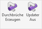
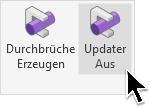
The Updater is disabled by default. The switch is labeled "Updater Off" and is grayed out.
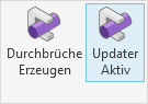
Tip: The Updater is designed to remain active at all times.
Let's now place a wall opening in a floor plan using Revit's "Place Component" feature.
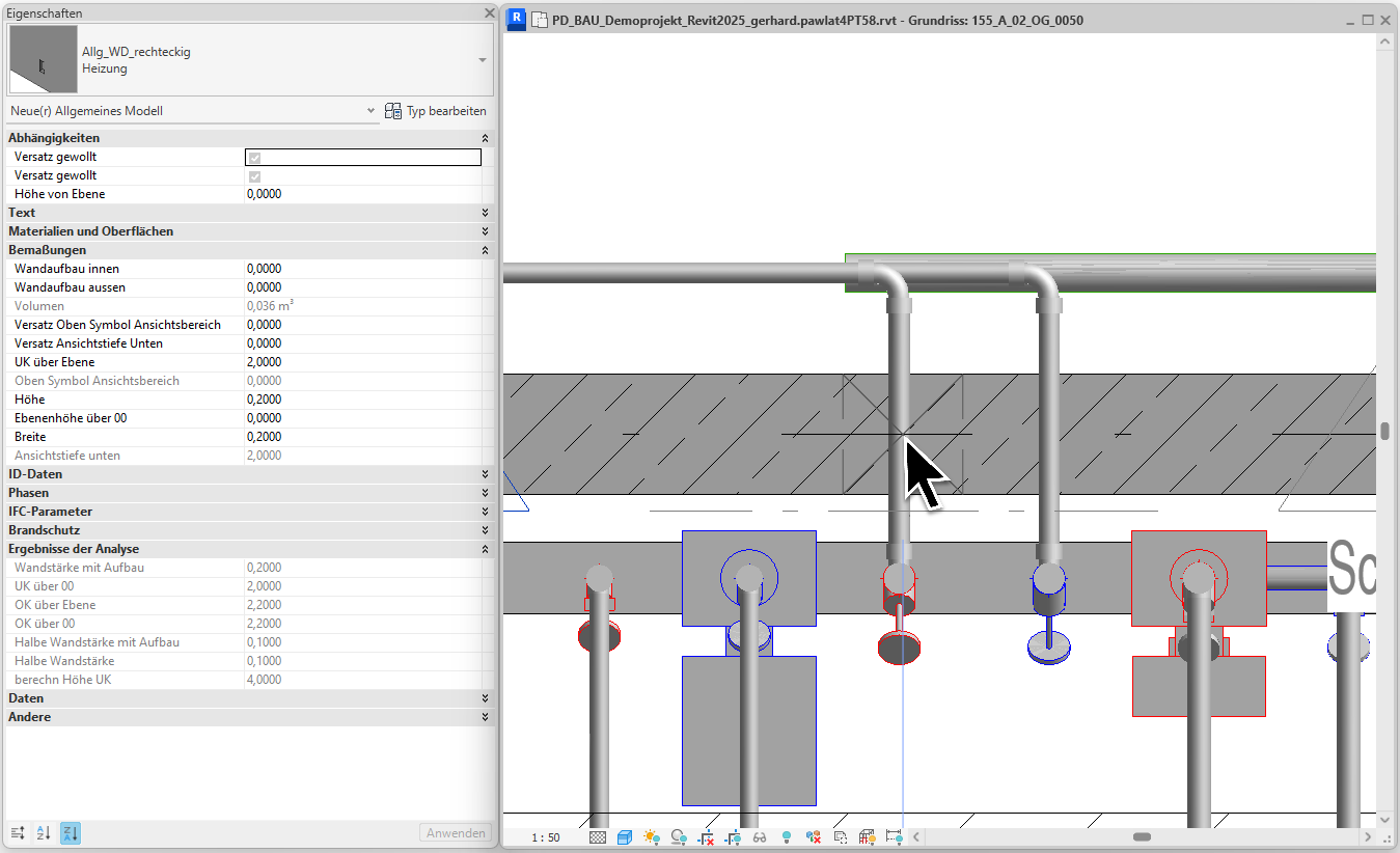
The cutout is positioned and updated automatically.
It can be labeled immediately; the label shows the correct value of UK +9,000 m.
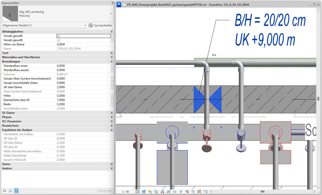
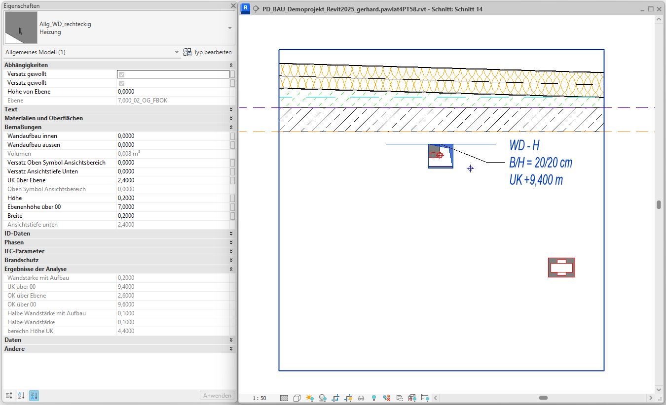
We switch to a section view to move the cutout to its target height.
The label shows the correct value UK +9,400 m.
Note:
When the Updater is active, the elevation parameters of openings are always kept up to date when placing or modifying them. As a result, labels always display the correct values.
Note:
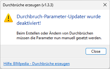
If you disable the updater, your breakthroughs will no longer be updated automatically. A warning will appear to alert you to this.
In this section, we would like to provide you with guidance on how to handle any misconduct that may occur.
- Cutout instances are created with the wrong family type:
Check whether the desired family types are available in the families you are using. "Create Cutouts" does not display a warning if family types are missing. In that case, the default type "TGA-General" is used for placement. If this is also not present in the family, the first type in the family is used for placement.
Always use the current and complete families from the Plandata Content to avoid such errors. For information on the logic of type assignment, see the "Family Types" section. - The depth of a cutout is incorrect and cannot be changed manually:
The "Depth" parameter of "Allg_DB_Area" cutouts is set automatically by the Updater. When the Updater is active, you cannot set this value yourself. If the value is set incorrectly for a component with complex geometry, temporarily use a cutout family with a different name. The Updater will then no longer be triggered for this family. Please report such behavior directly to our software development team.
The following features will be added or improved in future versions of "Create Cutouts."
- Additional categories such as duct accessories, pipe fittings, air diffusers, HVAC components, and plumbing fixtures are supported.
- A new family for fire protection penetrations is supported.
- Openings are assigned a number when placed (using the "Identifier" parameter).
- The column width of "Edit Configuration" and "Results Report" can be adjusted by the user by dragging.
- The first column of "Edit Configuration" is pinned to maintain an overview while scrolling.
- Checking penetrations should be possible in the active view without special check views. The feasibility of a check per base component instead of per penetration is being evaluated.
- If no FBOK reference level is found for a breakthrough, manual assignment will be enabled directly via the user interface.
- ...
If you would like to suggest a new feature, please contact our software development team directly.
1.5.0.0
- Revit 2026.0 through 2026.4 is now supported.
- The info icon opens the BIMpedia article.
- Pressing the F1 key opens the BIMpedia article.
1.5.1.0
- Automatic family assignment:
Now takes into account all families listed under "Assign families," regardless of the family type they contain. Previously, assignment was limited to families that included the family type defined as the default ("TGA_General"). This condition has been removed. - Manual family assignment:
Bugs have been fixed. - Project units:
All project units are now supported.
When creating wall openings, openings with incorrect heights were generated if the project units were not set to meters.
1.5.2.0
- Type Assignment:
An error in the assignment of family types has been fixed.
If no suitable penetration family type could be assigned based on the pipe discipline, a random family type was assigned. After the error was fixed, the defined default family type "TGA_General" is now assigned.
1.5.3.0
- Results Report:
The first row in the results report (Drill-down 1) was not updated when changes were made to the drill-down (e.g., width). The issue has been resolved. - Family assignment:
Errors in family assignment have been fixed. - Air ducts in the building model:
Openings for air ducts in the building model could not be created. This error occurred exclusively when working in a local copy of a central file. Air ducts in linked models were not affected.
The error has been fixed. - Control View - Select Linked Elements:
Previously, the selection of elements from linked models was disabled when creating control views. This restriction has now been removed. Elements from linked models can now be selected in the control views.
1.5.4.0
- Floor plans are now supported:
Floor plans are now supported in the "Generate automatically in active view" placement mode. - Override Breakthrough Layer:
The breakthrough layer can now be inherited from the active view.
By default, a matching FBOK layer is automatically searched for and assigned to the breakthrough.
The new "Override Layer" feature allows you to bypass this automatic assignment and instead adopt the layer from the active view. The "Override Layer" button is available in the "Create Manually" and "Create Automatically in Active View" placement modes. The button is active only in floor plans. - Navigation Window:
The "Confirm Position" button is disabled for invalid openings. - Project Base Point:
A Z-offset of the project base point from the internal origin was not taken into account. This led to errors in the creation of control views for wall openings. Furthermore, room detection was incorrect. The error has been fixed.
If you have any problems or questions, or if you have ideas or suggestions, please feel free to contact our customer service team. We look forward to hearing your suggestions for improvement!