In 4D planning, this refers to the ability to incorporate and simulate schedules and construction processes into a model. This provides a better basis for alternative planning and construction processes, better control over construction progress, faster billing, and a clearer overview of on-site operations, thereby improving the coordination of site setup and logistics.
Option 1: Using MS Project
- Create processes
Option 2: using a CSV file
- Select template file: "Schedule(Excel)_TEMPLATE.xlsx"
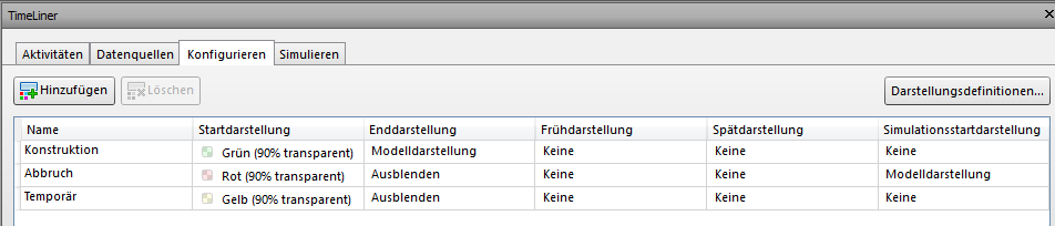
- Create activity types (predefined; additional types can be added)
| Activity Type/Process Type | What happens to the element |
| Construction | Created elements |
| Abort | cancelled elements |
| Temporary | Temporary elements |
- Each process should be on a separate line (e.g., "Build ground floor walls, replace existing ground floor doors," etc.)
- Specify dates
- Save as .csv
- Open with a text editor
- Replace all ";" with "," (under Edit -> Replace)
- Save as .csv
Create and define Revit parameters
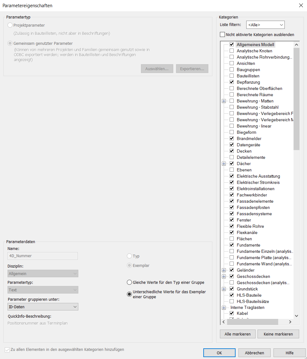
If the required 4D_... parameters have not already been created and defined in the template, they can be loaded into the project from the shared parameter list and assigned to the appropriate categories.
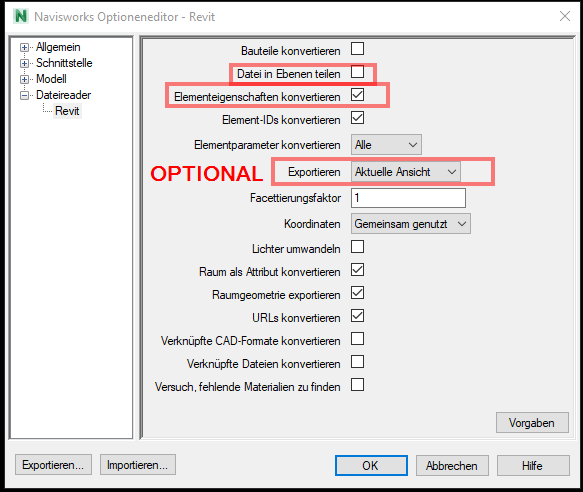
NWC Export Settings
Open NWC file
- Open Navisworks
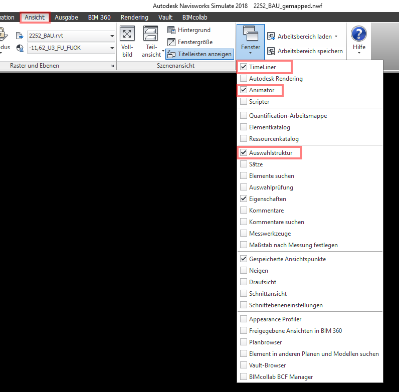
- Open the Timeliner, Animator, and Selection Tree windows.
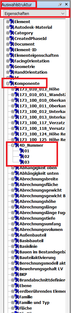
- Check whether the parameter 4D_Number is present in the selection structure under "Component".
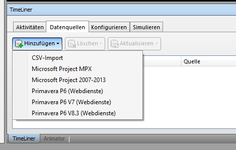
Import/synchronize schedule
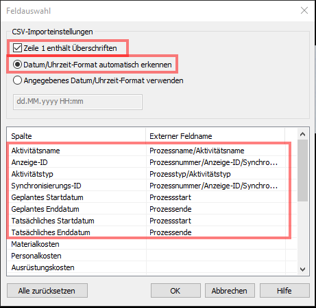
- Settings for CSV Import
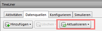
- Clicking "Update" creates the data as activities in Navisworks.
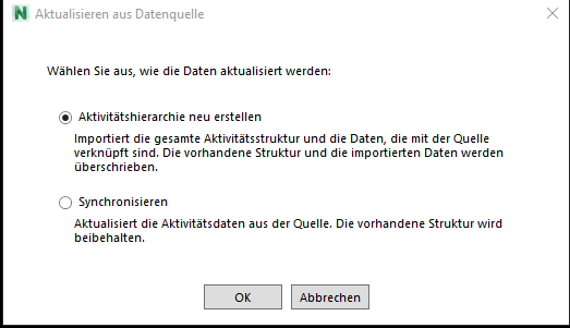
The activity hierarchy must be recreated the first time; after that, it will only be synchronized.
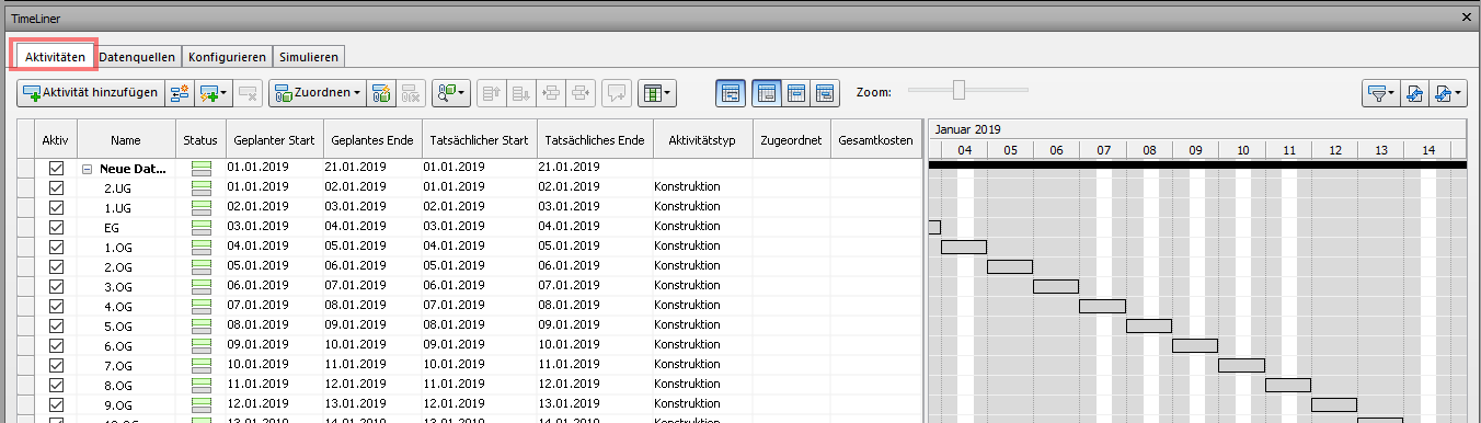
- Check whether a schedule has been created.
Automatic mapping
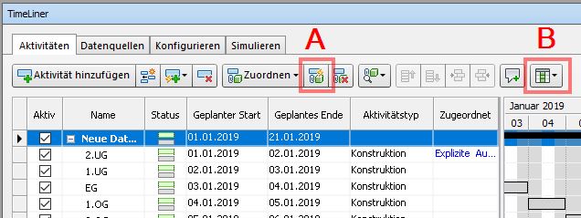
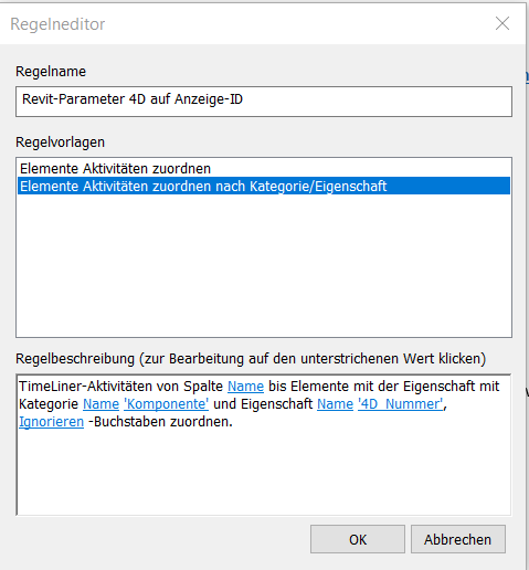
A. Automatically map the display ID and process number -> Apply rule.
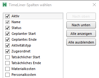
B. Select columns
- Check whether a selection is assigned to each process
Simulate and export
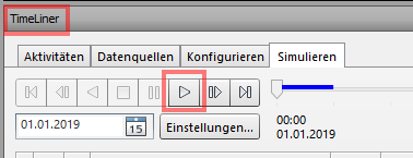
- Check whether the simulation is correct.
Animation (Optional)
- Open Animator
- Create each process to be simulated
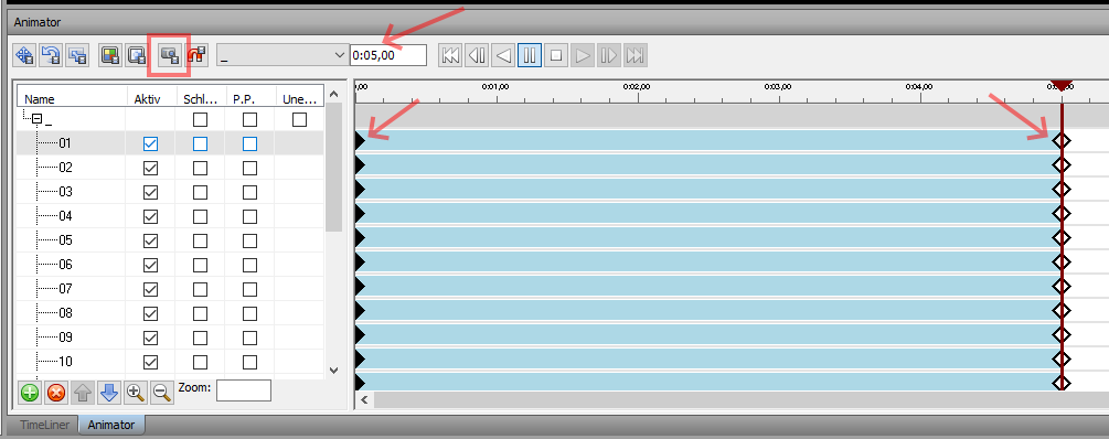
- Create a keyframe at 0:00 and 0:05.00. A diamond will then appear at the beginning and end, respectively.
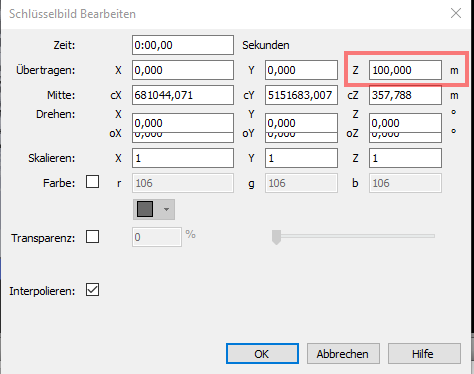
- Click on the respective start screen images and then click Edit.
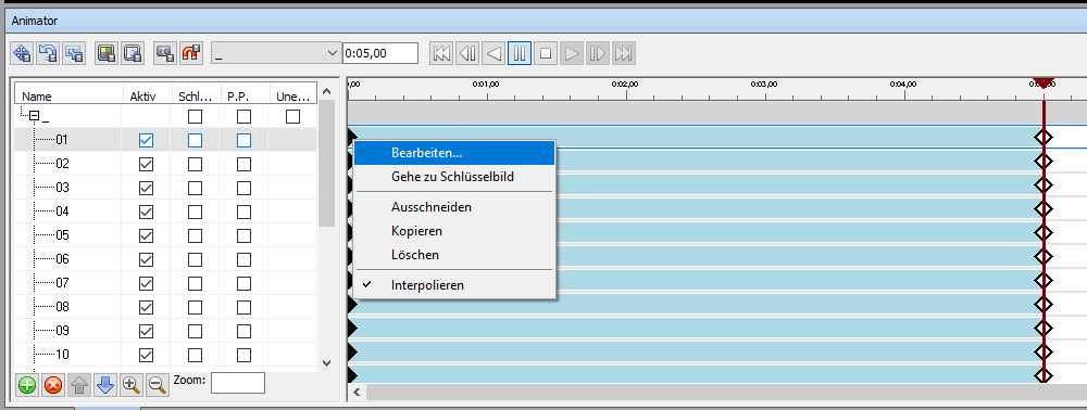
- Change position Z to 100,000 m